
Multi-frequency antenna

A multi-frequency antenna and antenna technology, which is applied to antennas, independent antenna unit combinations, and devices that enable antennas to work in different bands at the same time, can solve the problems of antennas that are not easy to manufacture, and achieve the effect of simple manufacturing process and maintaining radiated energy

Inactive Publication Date: 2008-01-16
FOXCONN (KUNSHAN) COMPUTER CONNECTOR CO LTD +1
View PDF1 Cites 6 Cited by
  • Summary
  • Abstract
  • Description
  • Claims
  • Application Information

AI Technical Summary

Problems solved by technology

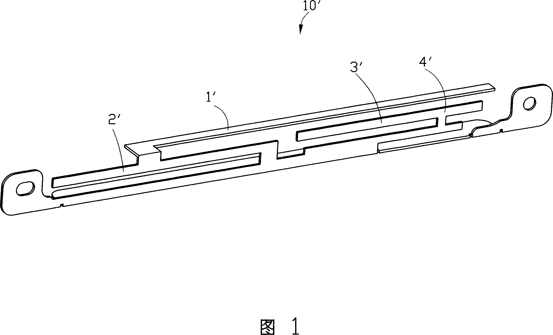
The layout of the antenna is arranged on a circuit board, which is easier to implement in this way; however, there is a plane inverted "F" antenna made of metal sheet among the antennas that are widely used in portable devices such as notebook computers. This kind of antenna does not have a circuit board to support it, and this method is not easy to process for these antennas

Method used


Image

  • Multi-frequency antenna
  • Multi-frequency antenna
  • Multi-frequency antenna

Examples


Embodiment Construction

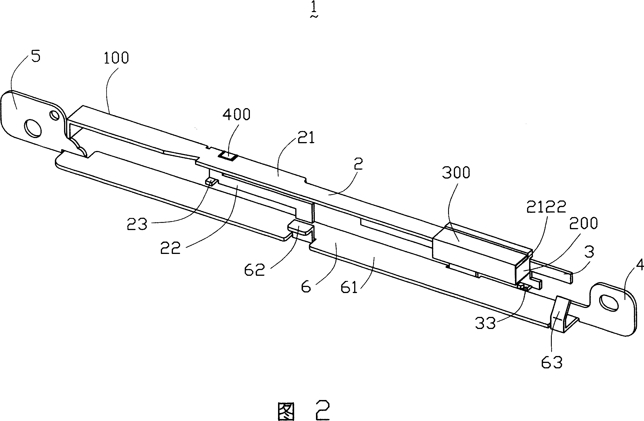
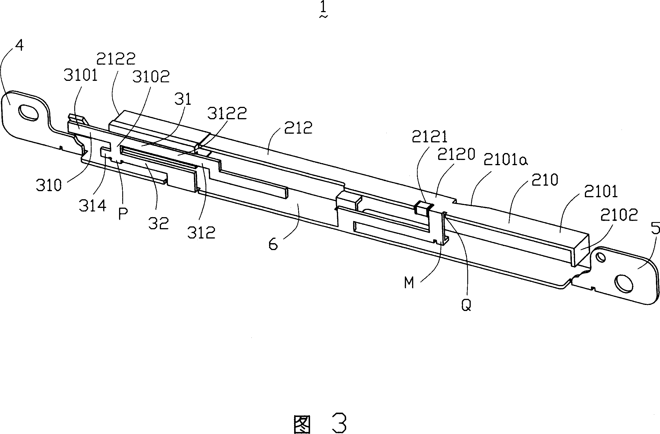
[0012] 2 to 4 are perspective views of a multi-frequency antenna provided according to a preferred embodiment of the present invention. The multi-frequency antenna 1 is composed of an antenna body 100, a plastic part 200 and a metal foil 300 pasted on the antenna body 100, and a ceramic passive element 400 welded on the antenna body 100, which includes the first wireless wide area network An antenna 2 , a second antenna 3 for wireless local area network, a ground part 6 shared by the two antennas, and installation parts 4 and 5 located on the ground part 6 . In this embodiment, the plastic part 200 , the metal foil 300 and the ceramic passive element 400 are all located on the first antenna 2 . The body 100 of the multi-frequency antenna 1 is made by stamping a metal sheet, and combines the wireless wide area network antenna and the wireless local area network antenna together. The grounding portion 6 has a first grounding portion 61 , an “L”-shaped metal piece 62 extending f...


PUM


Abstract

The invention discloses a multi-frequency antenna, which comprises a first antenna for wireless wan, a second antenna for wireless wan and a grounding part for both two antennas using. The low frequency of the first antenna is composed of a metal plate, a plastic part, an aluminum foil and a ceramic passive element.

Description

【Technical field】 [0001] The invention relates to a multi-frequency antenna, in particular to a multi-frequency antenna used in electronic equipment such as notebook computers. 【Background technique】 [0002] With the rapid development of mobile communication, the size of various electronic products is getting smaller and smaller, and the requirements for their internal components are also getting higher and higher. Due to the development of wireless network technology, more and more wireless access modes based on GPRS (General Packer Radio Service, General Packet Radio Service) and WLAN (Wireless Local Area Network, Wireless Local Area Network) are used in notebook computers. [0003] In the wireless communication process, the antenna is an essential and important component. Some portable terminals equipped with GPRS and WLAN dual-mode network cards will be equipped with two antennas to adapt to WWAN (Wireless Wide Area Network. WAN) and WLAN working frequency band require...

Claims


Application Information

Patent Timeline
IPC IPC(8): H01Q3/00H01Q5/00H01Q13/00H01Q21/30
Inventor 苏纹枫洪振达王舒嬿
Owner FOXCONN (KUNSHAN) COMPUTER CONNECTOR CO LTD
Learn More