
Profile extension device

A technology of body and detection strip, which is applied in the direction of instruments, mechanical counters/curvature measurement, measuring devices, etc., can solve the problems of inconvenient recording and sorting, and difficult adjustment of zero point, etc., to achieve convenient recording and processing, and fast detection and expansion speed , Intuitive recording and processing effect

Inactive Publication Date: 2008-01-09
葫芦岛市特种设备监督检验所
View PDF0 Cites 1 Cited by
  • Summary
  • Abstract
  • Description
  • Claims
  • Application Information

AI Technical Summary

Problems solved by technology

[0004] 1. The zero point is not easy to adjust
[0005] 2. The test data can only be read visually, which is not easy to record and organize

Method used


Image

  • Profile extension device
  • Profile extension device

Examples


Embodiment Construction

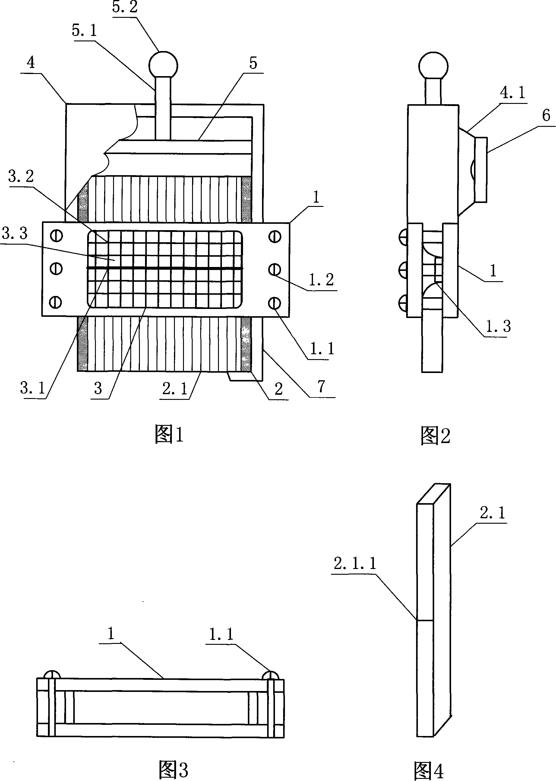
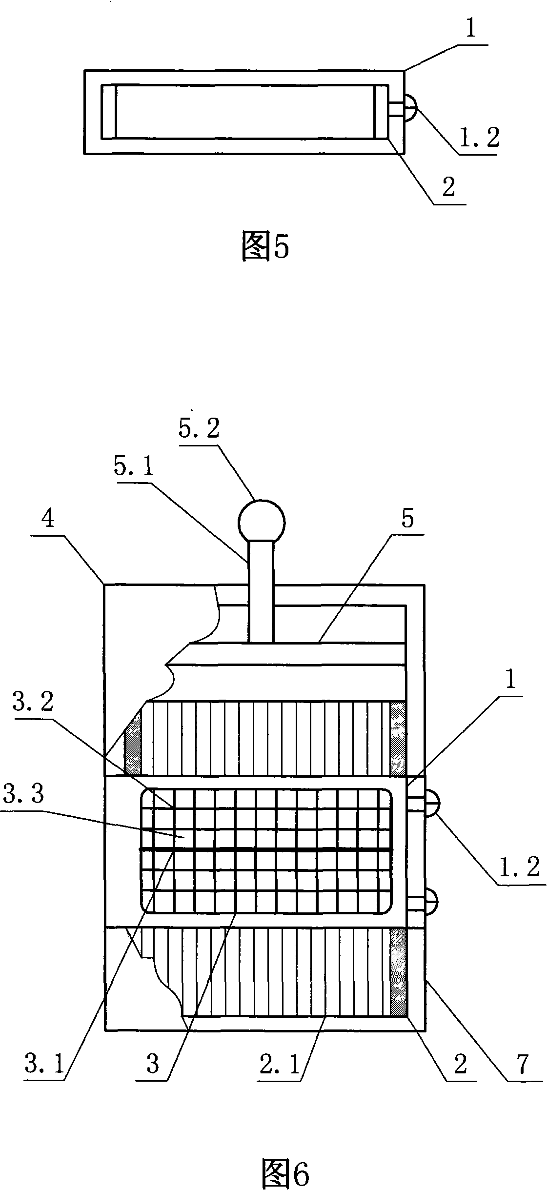
[0018] As shown in Figures 1, 2, 3, 4 and 5, a baffle 1 with an inner cavity is formed by a combination of plates or an integral form, and a window 3 is opened on one side of the baffle, and a transparent window is attached on the inner side of the window. Window plate 3.3, scale line 3.2 is engraved on the window plate, a number of detection strips 2.1 are interspersed and installed in the inner cavity, and detection strip track lines 2.1.1 are arranged on the detection strips, and the detection strips are placed on the edge baffles of the two detection strips 2, forming the shape extension device body. Install the zero-returning record box 4 on the upper part of the extension device body, and in the zero-returning record box, the zero-returning plate 5 is installed through the zero-returning lever handle 5.2 and the zeroing lever 5.1, and a light shield is provided at the rear of the zero-returning record box 4.1, a camera 6 is installed on the light shield, and a protective...


PUM


Abstract

The invention relates to an extension device which is used in testing the object shape or measuring sample. It is composed of the board or the baffle which has a lumen, on the side baffle opens a window, and inside affixed with a transparent window panels, carved on a scale line, installs the test bar in the lumen, and on which installs the test trochoid to compose the extension device. On the extension device installs on the upper-zero record box, inside installs the zero plate block mask by their adopted zero-handles and zero-zero plate, at the back of the zero plate installs a light block cover, and on which installs a camera, the lower end of the extension device installs a protect box. The invention can detect the concave or convex, that is, can be directly read data, but also can be stored the obtained graphics data through the camera method and archiving; it has fast extension velocity, intuitive and easy record and the effect of processing technology, is suitable for boiler, pressure vessel, and physical structure component profiling data retention occasions application.

Description

technical field [0001] The invention proposes a shape topping device used for object shape detection or sample measurement in the mechanical field. Background technique [0002] Before the present invention was proposed, there was a detection ruler for welding detection, its structure was: a number of retractable detection strips were installed between two flat plates, an observation port was opened on the flat plate on one side, and a A transparent sheet is attached to the inner side, and a scale line is set on the transparent sheet. The sides of the two plates are connected and fixed by bolts and compression springs. There are scale points on the test strip, which can slide up and down in the inner cavity of the test ruler. Before use, the scale point on the test strip should coincide with the zero scale line on the transparent sheet to be the zero point. When in use, press the test strip on the object to be tested. The detected surface shrinks and moves, and the scale po...

Claims


Application Information

Patent Timeline
IPC IPC(8): G01B5/20G01B5/02G01D9/42
Inventor 李继新陆少柏
Owner 葫芦岛市特种设备监督检验所
Learn More