Biconical antenna
A technology of biconical antenna and truncated cone, which is applied to resonant antennas, mid-position feeding between antenna endpoints, and radiating element structures, etc. Give special records of dimensions and other issues
- Summary
- Abstract
- Description
- Claims
- Application Information
AI Technical Summary
Problems solved by technology
Method used
Image
Examples
no. 1 approach
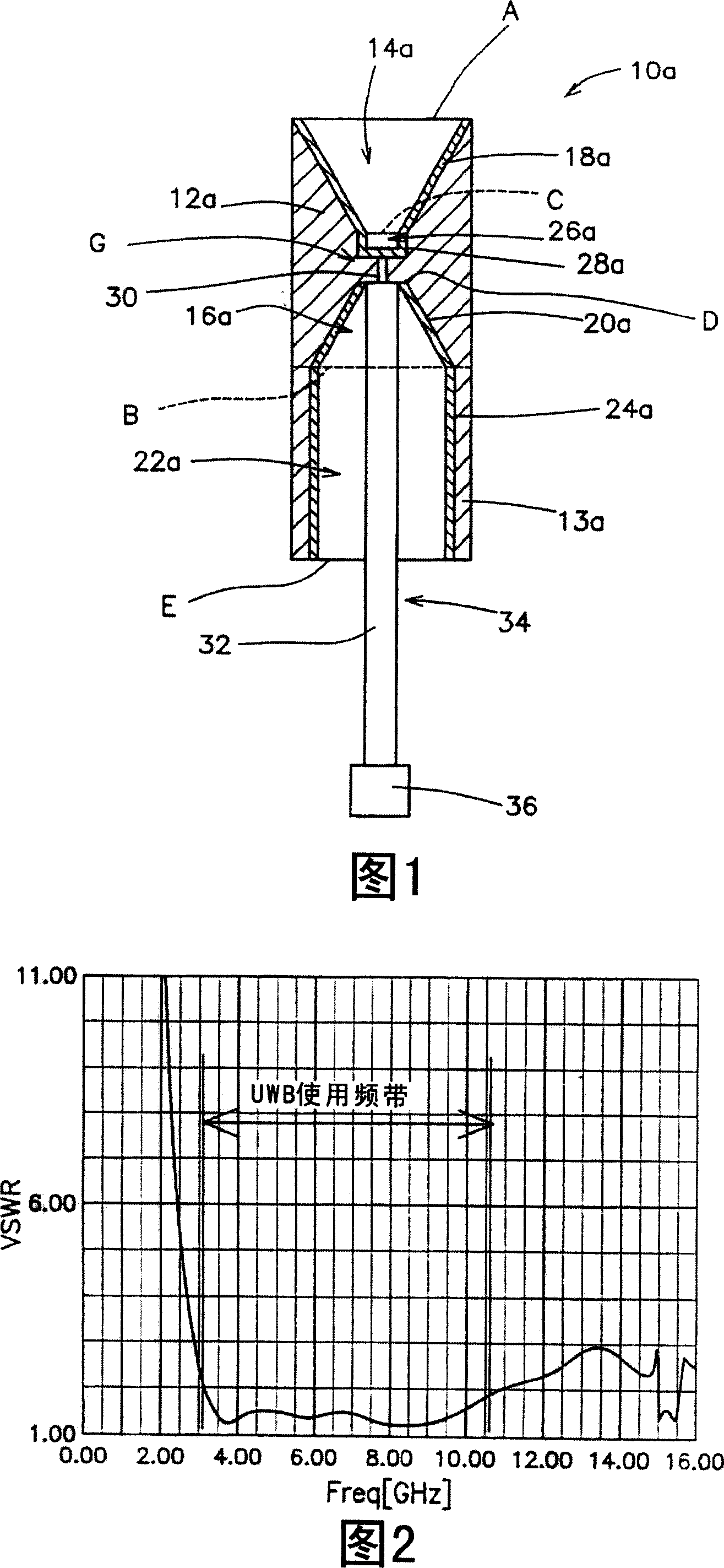
[0053] FIG. 1 is a cross-sectional view showing the structure of a biconical antenna 10a according to a first embodiment of the present invention. This biconical antenna 10a includes: a dielectric body 12a having two cavities 14a and 16a in the shape of a truncated cone, a cylindrical dielectric body 13a, a reflector 28a, a coaxial cable 34, a central conductor 30 of the coaxial cable, The shield conductor 32 of the coaxial cable, the connector 36, the power supply part 18a, the ground part 20a, and the ground reinforcing part 24a.
[0054] The power supply portion 18a is composed of a conductive film provided on the inner surface of a truncated conical cavity extending from the upper surface A of the cylindrical dielectric body 12a toward the center.
[0055] Likewise, the ground portion 20a is also composed of a conductive film provided on the inner surface of a truncated conical cavity extending from the lower surface B of the cylindrical dielectric body 12a toward the cent...
Embodiment 1
[0100] As shown in FIG. 12, Embodiment 1 gives the case where the power supply portion 112a and the ground portion 114a have the same truncated cone shape. The power supply part 112a and the ground part 114a have the same truncated conical shape, are coaxial with the gap 16a as the center, and are formed in opposite directions to form a symmetrical shape. The diameters of the bottoms B and B' of the truncated cone shape are both 15 mm, the diameters of the tops A and A' are both 2.4 mm, and the heights are also both 13 mm. The respective tops A and A' of the feeding portion 112a and the grounding portion 114a are parallel. The gap 106a is 1.5mm. The dielectric constant of the dielectric body 118 is 3.6.
[0101] The simulation results of the biconical antenna shown in FIG. 12 will be described.
[0102] 13 is a graph showing simulation results in the case of Example 1 of the biconical antenna of the second embodiment. In this simulation, the coaxial cable 124 is set to ter...
Embodiment 2
[0122] Example 2 is a case where the shapes of the power feeding part 112b and the ground part 114a are different.
[0123] FIG. 19 is a schematic structural diagram of a biconical antenna in which the heights of the power supply part 112b and the ground part 114a are different. The height of the truncated cone shape of the power feeding portion 112b is higher than the height of the truncated cone shape of the ground portion 114a. In addition, a reflective portion 130b is provided at the top A of the power feeding portion 112b. The reflection part 130b has a disk shape. The reflection part 130b has the function of smoothly removing high frequency frequencies. In addition, a configuration without the reflecting portion 130b may also be used. In addition, there is a ground reinforcing part 128b connected to the bottom B' of the ground part 114b. For example, the diameter of the bottom B' of the ground portion 114b is made the same as the diameter of the ground reinforcement ...
PUM
| Property | Measurement | Unit |
|---|---|---|
| Height | aaaaa | aaaaa |
| Height | aaaaa | aaaaa |
Abstract
Description
Claims
Application Information
 - R&D
- Intellectual Property
- Life Sciences
- Materials
- Tech Scout
- Unparalleled Data Quality
- Higher Quality Content
- 60% Fewer Hallucinations
Browse by: Latest US Patents, China's latest patents, Technical Efficacy Thesaurus, Application Domain, Technology Topic, Popular Technical Reports.
© 2025 PatSnap. All rights reserved.Legal|Privacy policy|Modern Slavery Act Transparency Statement|Sitemap|About US| Contact US: help@patsnap.com


