
Air conditioning device

An air-conditioning device, air technology, applied in air-conditioning systems, space heating and ventilation, heating methods, etc., can solve problems such as airflow short circuit, and achieve the effect of preventing short circuit phenomenon

Active Publication Date: 2008-01-02
PANASONIC CORP
View PDF1 Cites 19 Cited by
  • Summary
  • Abstract
  • Description
  • Claims
  • Application Information

AI Technical Summary

Problems solved by technology

[0005] However, if the above-mentioned existing air conditioner structure is adopted, although the air flow can be effectively blown horizontally or upward during cooling, on the other hand, under certain conditions such as the temperature and air volume of the exhaust air flow, a part of the exhaust air flow will occur. The short circuit phenomenon of the airflow sucked in from the lower part of the air inlet

Method used


Image

  • Air conditioning device
  • Air conditioning device
  • Air conditioning device

Examples


Embodiment Construction

[0024] An embodiment of the present invention will be described in detail below with reference to the accompanying drawings. At the same time, it should be pointed out that the technical scope of the present invention is not limited by this embodiment.

[0025] (Example)

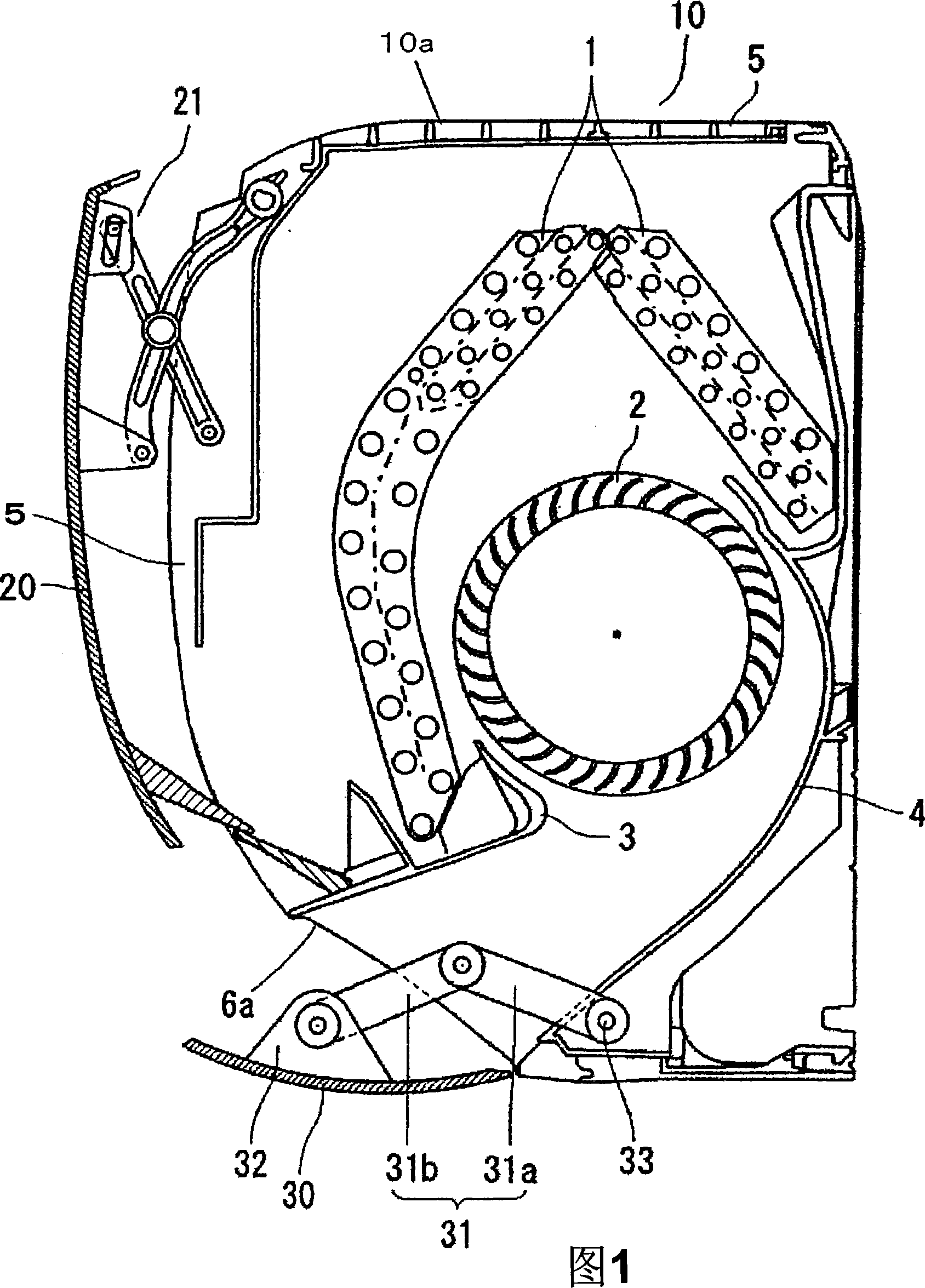
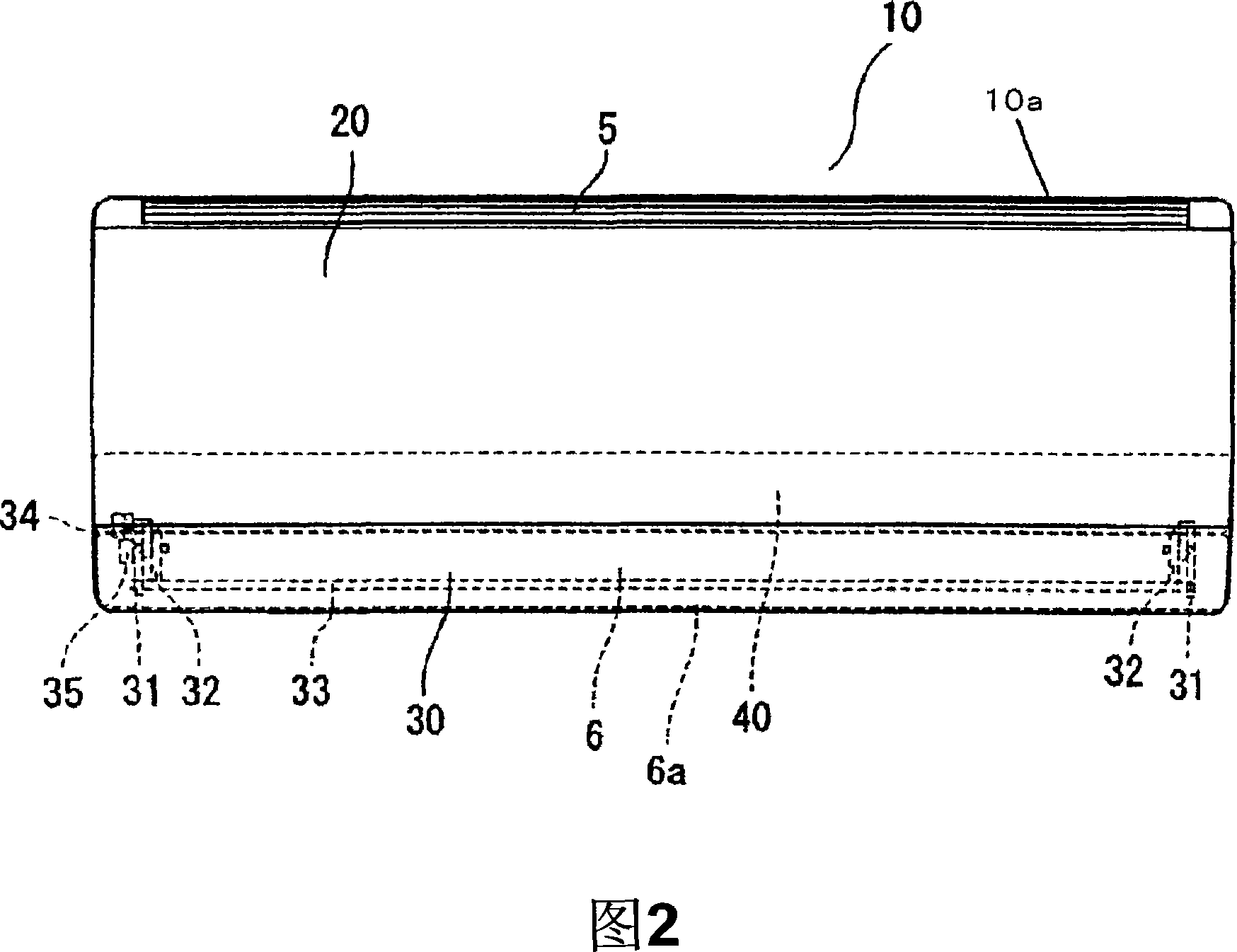
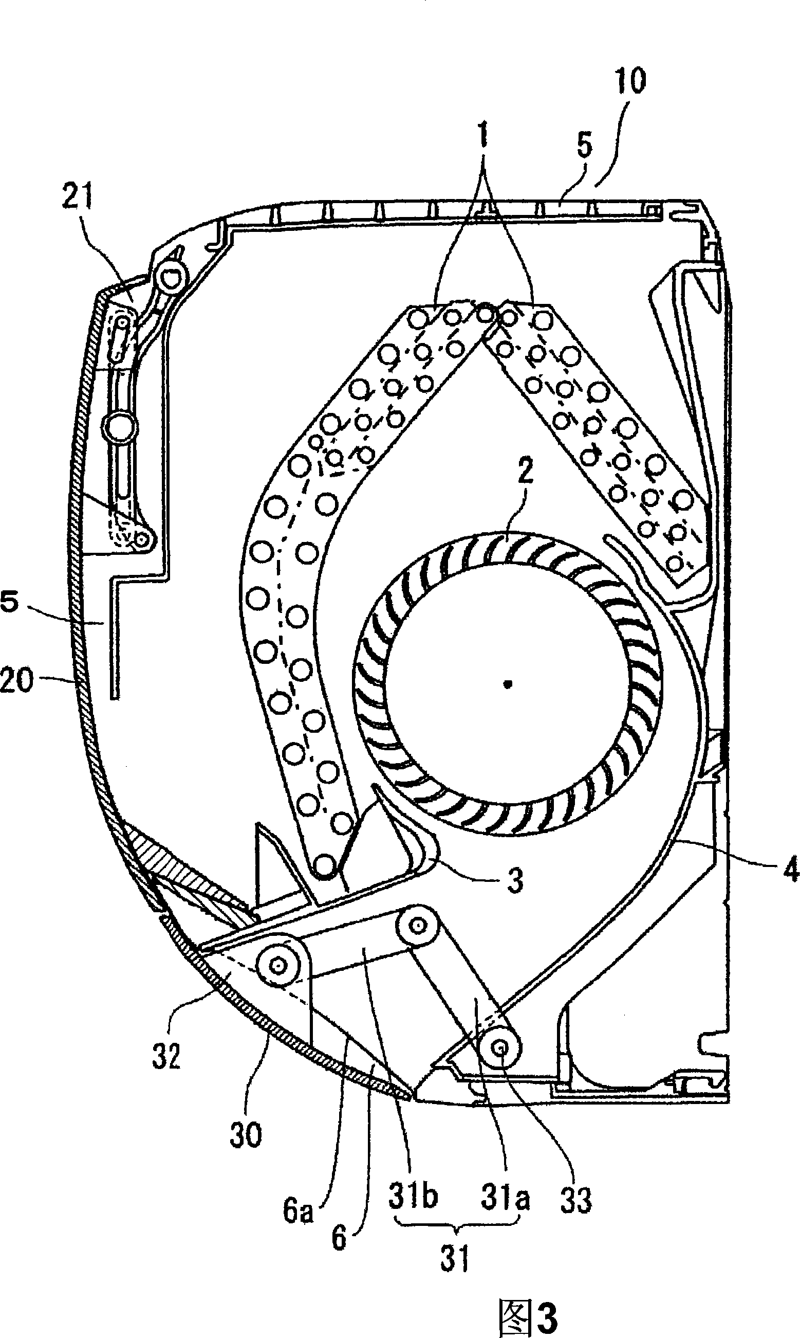
[0026] An air conditioner in one embodiment of the present invention will be described below using FIGS. 1 to 7 . FIG. 1 is a longitudinal sectional view of the air conditioner of this embodiment, and FIG. 2 shows a front view of the air conditioner in FIG. 1 . In addition, the same symbols are used for the same components as those of the air conditioner in the prior art, and repeated description thereof will be omitted here.

[0027] The body 10 a of the air conditioner 10 is provided with a heat exchanger 1 , a blower fan 2 , a water tray 3 and a diffuser 4 . The heat exchanger 1 is arranged on the upstream side of the blower fan 2 , and the water receiving pan 3 is arranged on the lower end side of the...


PUM


Abstract

The present invention provides an air conditioner without air exhausting short circuit phenomenon, and the air conditioner includes the following components: a machine body (10a) which is arranged with a heat exchanger (1) at the inner side and an air inlet (5); a panel (20) which opens / closes the air inlet; a starting fan (2) which sucks indoor air from the air inlet and makes the air through the heat exchanger and discharges the air which has past the heat exchanging from the air outlet (6); and a wind direction alternating blade (30) which is arranged on the air outlet and is used to alter the wind direction. In the refrigerating operating mode the wind direction altering blade lies on the end at one side of the machine body and is contacted firmly to the lower side of the downstream side end (6a) of the air outlet, and operating to the wind altering blade to make the line which connects the lower side of the downstream side end of the air outlet and the other end of the wind direction altering blade to the same position or the upper position of the horizontal line which traverses the lower extreme of the downstream side end of the air outlet to restrain the gas current flowing into the air inlet from the lower part of the panel.

Description

technical field [0001] The invention relates to an air conditioner for heating and cooling a room. Background technique [0002] The structure of the existing air conditioner is shown in FIG. 8 . Fig. 8 is a cross-sectional view showing a schematic configuration of a conventional air conditioner. [0003] As shown in Figure 8, the existing air conditioner 10 is provided with: a heat exchanger 1; a blower that sucks indoor air and makes it pass through the heat exchanger 1, and then discharges the heat-exchanged air from the air outlet 6; The fan 2; the diffuser 4 forming the airflow channel between the blower fan 2 and the air outlet 6; the water receiving tray 3 that receives the condensed water generated and dropped in the heat exchanger 1; The wind direction changing blade 30 of the airflow direction; the arm 31 on which the wind direction changing blade 30 is installed on the top; and the arm drive motor 34 driving the arm 31 to rotate. In order to create a comfortabl...

Claims


Application Information

Patent Timeline
Patent Type & Authority Applications(China)
IPC IPC(8): F24F1/00F24F13/10F24F11/02F24F13/14F24F13/20
Inventor 杉尾孝向井靖人清水努海老原正春清水昭彦
Owner PANASONIC CORP
Learn More