Thin plate combined type photocatalyst carrier structure
A photocatalyst and combined technology, applied in the direction of catalyst carrier, physical/chemical process catalyst, chemical instrument and method, etc., can solve the problems of no longer providing surface area and small effective surface area
Inactive Publication Date: 2011-01-05
杨小明
View PDF0 Cites 3 Cited by
- Summary
- Abstract
- Description
- Claims
- Application Information
AI Technical Summary
Problems solved by technology
In the existing photocatalyst processor, some commonly used carriers include metal foam, porous ceramic material, aluminum honeycomb filter screen, wire mesh, non-woven fabric, etc. These carriers have a high specific surface area, but these carriers themselves are There are many small branches in the shape of filaments, strips, blocks, and sheets that are interlaced and combined. These small branches in the form of filaments, strips, blocks, and sheets overlap and block each other. When irradiated with ultraviolet light When using a linear (column) light source (such as a straight ultraviolet lamp tube), in fact, due to the linear propagation characteristics of light, only the small branch blocks on the outermost side close to the light source can be irradiated by ultraviolet light, while The backlight surface of the small branch, and the surface of many other small branches in the shadow formed by the small branch irradiated by the ultraviolet light cannot be irradiated by the ultraviolet light, so that the photocatalyst on it cannot be effectively excited. It affects the photocatalytic efficiency of the system, so the effective surface area of these photocatalysts on photocatalyst carriers with high specific surface area is very small when irradiated by ultraviolet rays.
Therefore, under a certain volume, the above-mentioned carrier can no longer provide more effective surface area that can be irradiated by ultraviolet rays, forming a bottleneck that is difficult to break through in the practical application of this photocatalyst technology.
Method used
View moreImage
Smart ImageViewing Examples


Examples
Embodiment Construction
Login to View More PUM
 Abstract
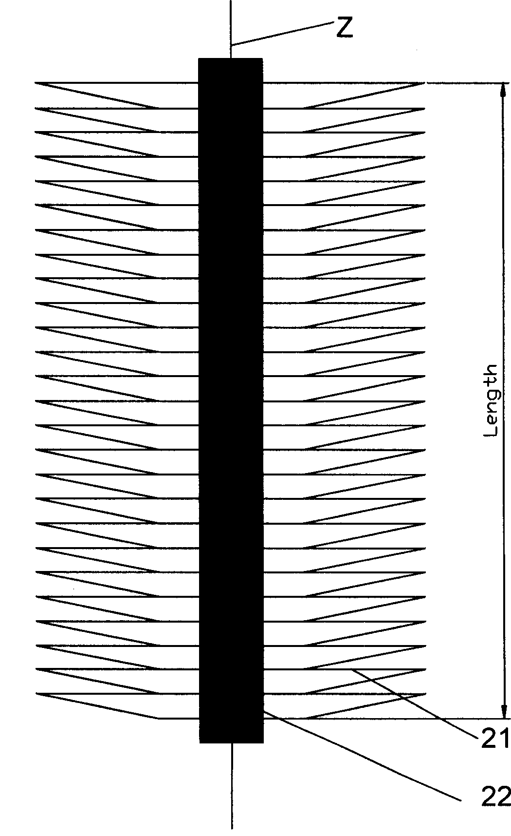
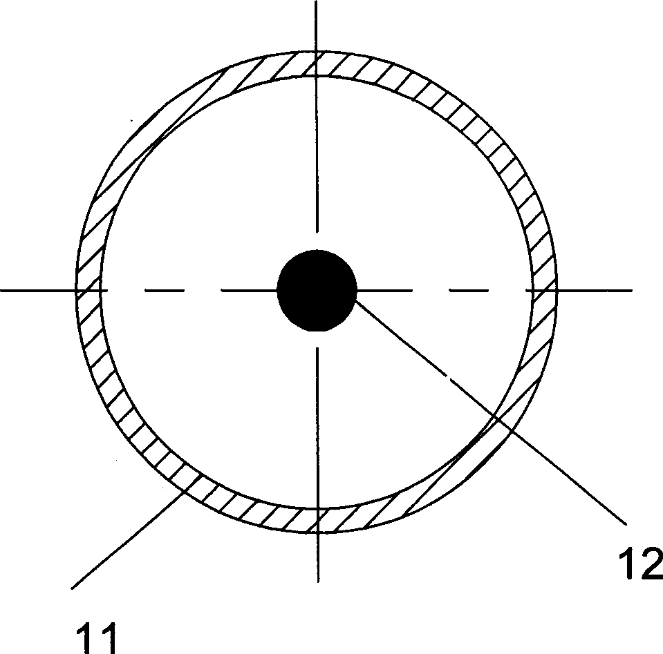
The invention discloses a thin-plate combined photocatalyst carrier structure, comprising several thin plates and ultraviolet light source. Several thin plates are arranged in laminated shape on the vertical axis direction of ultraviolet light source. Ultraviolet light source passes through the middle part among thin plates. Photocatalyst is carried on the surface of each thin plate and gaps for fluid flow are provided among thin plates. The photocatalyst carrier structure can make full use of linear propagation characteristic of ultraviolet light and make photocatalyst carrier obtain ultra-large ultraviolet irradiation ratio surface area. At the same time by adding the number of thin plates or developing blade dimension of thin plate arranging position of thin plate can be adjusted correspondingly to obtain larger ultraviolet irradiation ratio surface area. After the thin-plate combined photocatalyst carrier structure is applied in contamination treatment system, higher treating efficiency can be obtained. The invention provides technical support for practical application of contamination treatment system by photocatalyst. At the same time invest and use costs of treatment systemare decreased.
Description
Thin plate combined photocatalyst carrier structure technical field The invention relates to components in a photocatalyst processor for filtering pollutant fluids, and more specifically refers to a thin-plate combined photocatalyst carrier structure. Background technique The photocatalytic properties of photocatalysts (such as nano-titanium dioxide) were discovered by Professor Fujiyu Akira in Japan in 1972, and have been extensively studied and applied so far. The basic principle of photocatalysis is: when semiconductor oxide (such as titanium dioxide) nanoparticles are irradiated by photons (such as ultraviolet light) with energy greater than the forbidden band width, electrons transition from the valence band to the conduction band, generating electron-hole pairs. Electrons are reducing, and holes are oxidizing. Holes react with OH- on the surface of oxide semiconductor nanoparticles to generate highly oxidizing OH radicals. Active OH radicals can oxidize many refracto...
Claims
Login to View More Application Information
Patent Timeline
 Patent Type & Authority Patents(China)
IPC IPC(8): B01J32/00
Inventor 杨小明
Owner 杨小明
Features
- R&D
- Intellectual Property
- Life Sciences
- Materials
- Tech Scout
- Unparalleled Data Quality
- Higher Quality Content
- 60% Fewer Hallucinations
Learn More Browse by: Latest US Patents, China's latest patents, Technical Efficacy Thesaurus, Application Domain, Technology Topic, Popular Technical Reports.
© 2025 PatSnap. All rights reserved.Legal|Privacy policy|Modern Slavery Act Transparency Statement|Sitemap|About US| Contact US: help@patsnap.com