
Varied fuel cell oxidant flow channel depth resulting in fewer cooler plates

A fuel cell and fuel cell stack technology, applied in the directions of fuel cell additives, fuel cells, fuel cell grouping, etc., can solve problems such as affecting the water balance of fuel cell stacks, shortening the life of membranes or other temperature-sensitive components, etc. The effect of air utilization, size reduction, maintaining average temperature

Inactive Publication Date: 2007-12-19
INT FUEL CELLS
View PDF0 Cites 7 Cited by
  • Summary
  • Abstract
  • Description
  • Claims
  • Application Information

AI Technical Summary

Problems solved by technology

[0003] If more fuel cells are interposed between sequentially arranged cooler plates, the fuel cells further away from the cooler plates, especially those located in the center of said fuel cells, experience higher temperatures, This affects the water balance of the entire fuel cell stack and shortens the life of membranes or other temperature sensitive components

Method used


Image

  • Varied fuel cell oxidant flow channel depth resulting in fewer cooler plates
  • Varied fuel cell oxidant flow channel depth resulting in fewer cooler plates

Examples


Embodiment Construction

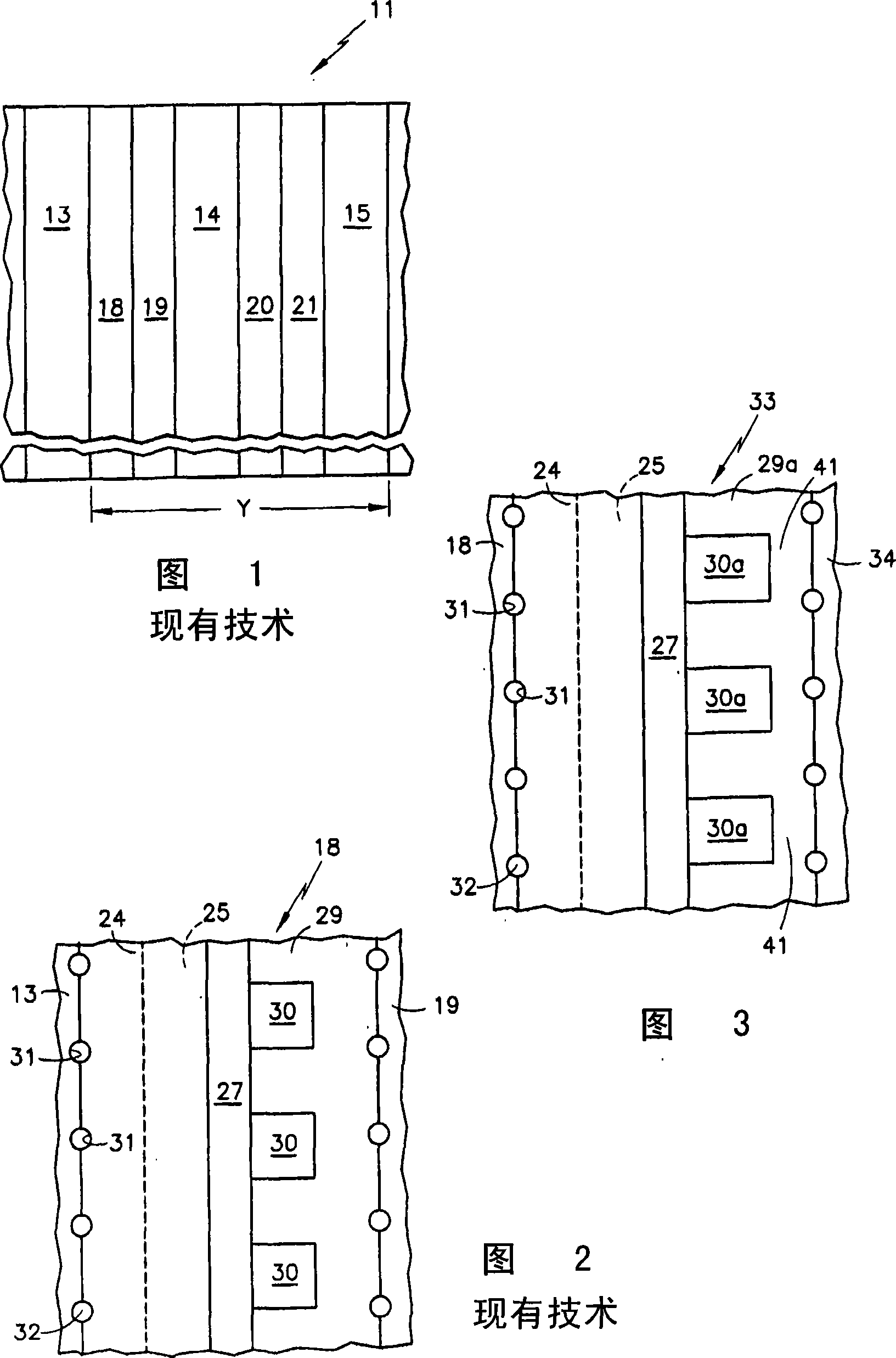
[0016] Referring to FIG. 1, fuel cell stack 11 includes a plurality of cooler plates, cooler plates 13-15 being shown. The fuel cell stack 11 also includes a large number of fuel cells, only fuel cells 18-21 being shown. Each of the fuel cells 18-21 is adjacent to one of the cooler plates 13-15 such that there are only two fuel cells between each pair of cooler plates.

[0017] The fuel cell 18 is exemplary and not drawn to relative or precise scale. Each fuel cell includes a hydrophilic porous fuel gas reactant flow field plate 24 with hydrophilic porous fuel flow field channels 25 disposed therein. Each fuel cell also includes an electrolyte assembly 27, which in the case of a proton exchange membrane, a polymer electrolyte membrane (PEM) fuel cell, includes a membrane and a catalyst on either side thereof. Each fuel cell also includes an oxidant gas flow field plate 29 that includes an oxidant gas flow channel 30 . Each reactant gas flow field plate 24 , 29 has a groove ...


PUM


Abstract

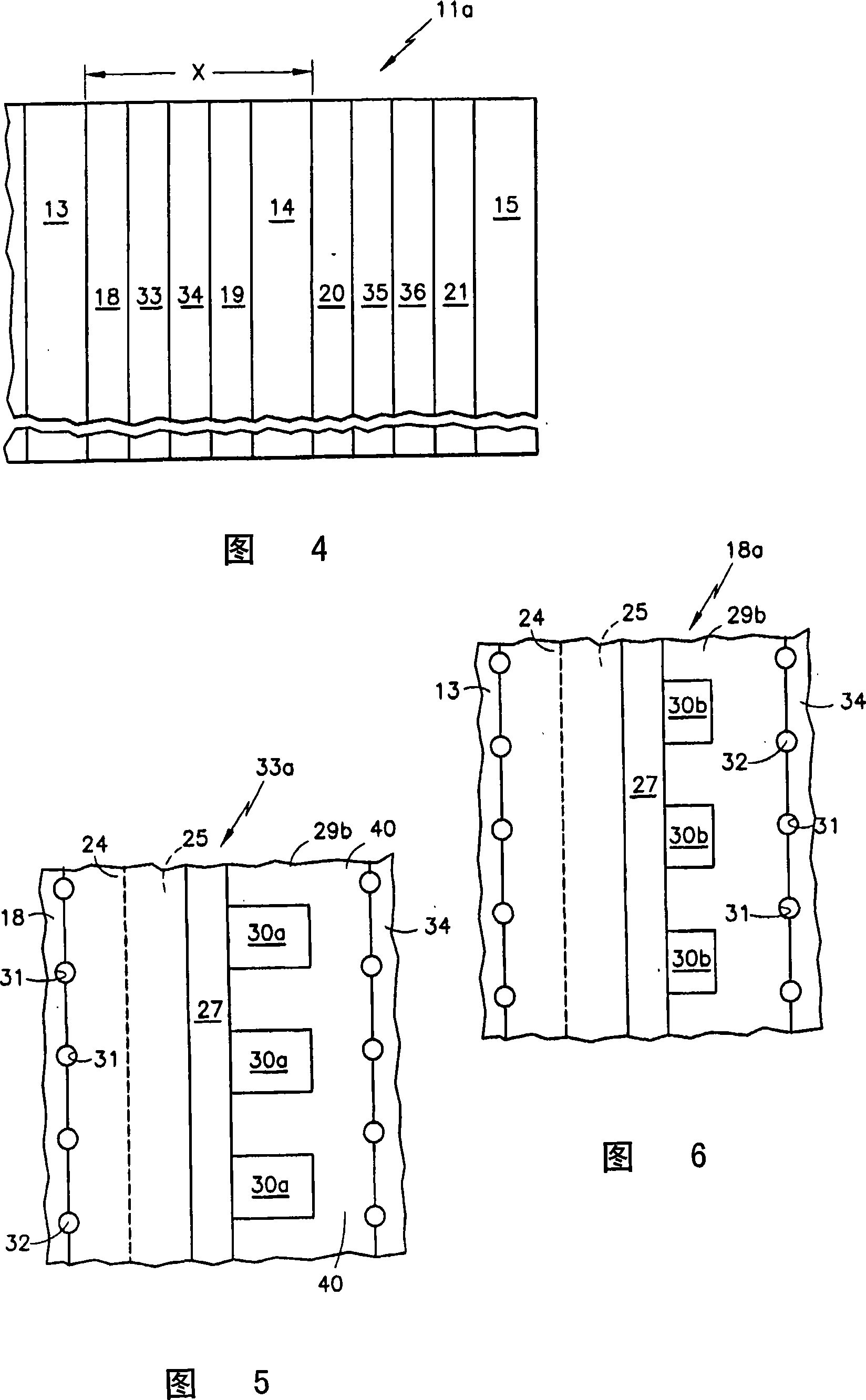
In a fuel cell stack ( 11 a), a larger number of fuel cells ( 18-21, 33-36 ) are interposed between successive cooler plates ( 13-15 ) without creating excessively high temperatures in those fuel cells ( 33-36 ) which are remote from the cooler plates, by virtue of increased air flow in air flow field channels ( 30 a) which are deeper in fuel cells ( 30-36 ) remote from the cooler plates, compared with the flow field channels ( 30, 30 b) which are in fuel cells ( 18-21 ) adjacent to the cooler plates. The thickness of air flow field plates ( 29 b) may be increased to accommodate the increased depth of the air flow channels ( 30 a). Fuel cells ( 18 a) adjacent the cooler plate may have air flow field channels ( 30 b) which are more shallow than normal whereby increased air utilization therein will be balanced by decreased air utilization in the cells ( 33-36, 33 a) having deeper air flow channels ( 30 a); in this case, the channels ( 30 a) may be normal or deeper than normal.

Description

technical field [0001] The present invention relates to providing a deeper oxidant flow channel depth in a fuel cell located farther from a cooler plate than in a fuel cell adjacent to the coolant plate, thereby allowing a greater amount of fuel to exist between sequentially arranged cooler plates battery while maintaining an average fuel cell stack temperature profile and air utilization. Background technique [0002] In many types of fuel cell stacks, whether anode water management and cathode water management are active (with pumps) or passive (without pumps), the fuel cell stack is subjected to coolers separated by groups of fuel cells Plate cooling. In some fuel cell system designs, as few as two fuel cells may be placed between sequential cooler plates. Since the cooler plates do not contribute to the voltage or power generation of the fuel cell stack, the power density of the fuel cell system and the end-to-end voltage of the fuel cell stack are inversely related to...

Claims


Application Information

Patent Timeline
Patent Type & Authority Applications(China)
IPC IPC(8): H01M8/04H01M8/12H01M8/24
CPCH01M8/241Y02E60/50H01M2250/20H01M2008/1095H01M8/04029H01M8/0258H01M8/023H01M8/04014Y02T90/32H01M8/04089H01M8/0267H01M8/0265H01M8/24H01M8/2457Y02T90/40H01M8/02H01M8/04
Inventor J·P·迈尔斯
Owner INT FUEL CELLS
Learn More