Eureka AIR delivers breakthrough ideas for toughest innovation challenges, trusted by R&D personnel around the world.

Built-in magnetic energy generator magnetic light

A generator and magnetic energy lamp technology, which is applied to discharge lamps, energy-saving lighting, lighting devices, etc., can solve the problems of complex circuit design, large loss and power consumption, and high degree of conduction interference of high-frequency electromagnetic radiation, so as to improve the electromagnetic conversion efficiency. , the effect of increasing the electromagnetic induction intensity and expanding the range of use

Active Publication Date: 2007-11-28
李进
View PDF0 Cites 12 Cited by
  • Summary
  • Abstract
  • Description
  • Claims
  • Application Information

AI Technical Summary

Problems solved by technology

However, since the electrodeless lamp only has a pear-shaped lamp body shape, and only a ferrite magnetic material electromagnetic coupling form placed in the middle of the lamp body at the bottom, the resonant operating frequency set at 2.6MHz to 2.8MHz makes the circuit Complex design, difficult suppression, complex circuit and high cost
The generated conduction interference, high-frequency electromagnetic interference and high-frequency electromagnetic radiation are large, the electromagnetic conversion efficiency is low, the loss and power consumption is large, the temperature rises, and the product and circuit are unreliable.

Method used


Image

  • Built-in magnetic energy generator magnetic light
  • Built-in magnetic energy generator magnetic light
  • Built-in magnetic energy generator magnetic light

Examples


Embodiment Construction

[0071] The present invention will be further described below in conjunction with the accompanying drawings and embodiments.

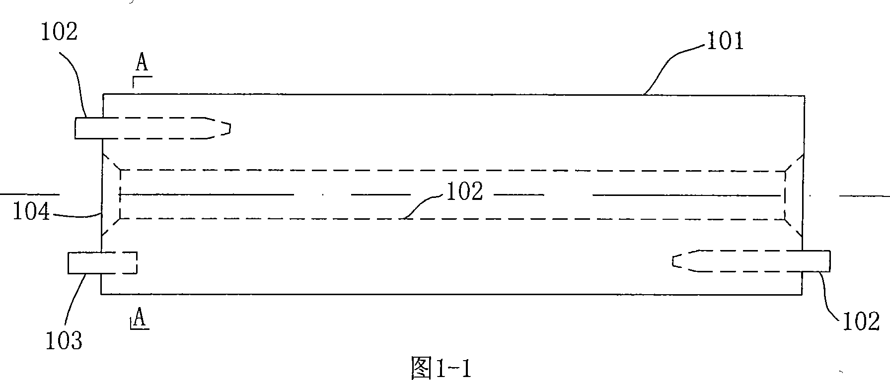
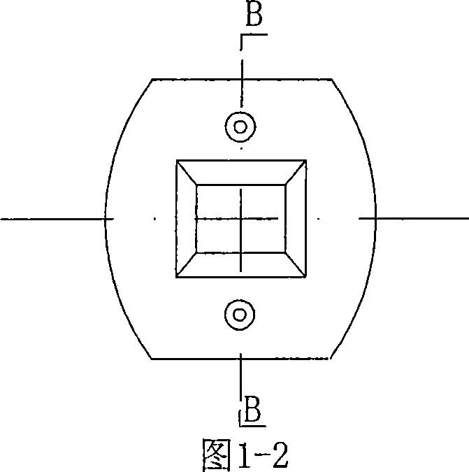
[0072] The built-in magnetic energy generator type magnetic energy lamp of the present invention is coupled with a magnetic energy lamp to drive a pulse transformer, or an inverter or alternating circuit formed by a half-bridge or full-bridge drive IC; Or the hollow glass lamp body with built-in holes is composed of three parts.

[0073] The invention utilizes the alternating circuit of the magnetic energy lamp and the built-in magnetic energy generator to carry out electromagnetic coupling and electromagnetic induction, replaces the filaments and electrodes used in traditional lighting lamps, and inserts correspondingly into the hollow glass lamp body coated with fluorescent powder material with built-in holes Form a magnetic energy lamp.

[0074] The magnetic energy generator of the present invention is attached with an insulating frame, and an elect...


PUM


Abstract

The invention discloses a light lamp in particular to an internally-arranged magnetic energy generator form magnetic energy lamp that the internally-arranged magnetic energy generator produces the electromagnetic induction and activates fluorescent powder to light. The invention includes the lamp body, the lamp body isn' t equipped with less than a penetrating hole or an internally-arranged hole, the penetrating hole or the internally-arranged hole isn' t equipped with less than the magnetic energy generator, the magnetic energy generator and the coupled driving impulse transformer of the magnetic energy lamp or the semi-bridge, the contravariant formed by the general bridge driving IC, the alternating circuit proceed with electromagnetic coupling or electromagnetic induction; two edges of the penetrating hole and two edges of the lamp body outer casing are sealed and form the vacuum cavity of the lamp body, the vacuum cavity of the lamp body charges the inactive gas and phosphor powder painted by the rare earth. The invention provides the simple structure, the various shapes, which reduces resonance frequency of the no electrode lamp from 2.6MHZ-2.8MHZ and the temperature of the circuit, the magnetic body and the lamp body, improves the electromechanical conversion efficiency from 25%-36%, increases two times-four times electromechanical induction density, and expands the application range of the magnetic energy lamp.

Description

technical field [0001] The invention relates to an illuminating lamp in the field of illumination, in particular to a magnetic energy lamp which generates electromagnetic induction by a built-in magnetic energy generator and activates fluorescent powder to emit light. Background technique [0002] Common lighting uses filaments and electrodes to emit light, which has low energy efficiency and short life. At present, the decay of compact fluorescent lamps is greater than 20% after 2000 hours, the efficiency of high-power compact fluorescent lamps is 48-53Lm / W, the input power of compact fluorescent lamps is 3W-120W, and the power factor of compact fluorescent lamps is 0.6-0.95, although it is higher than ordinary lighting The lamp has made great progress, but the effect of use is still not ideal. The input power of the new electrodeless lamp is 23W ~ 165W, which was reported in the book "Light Source and Lighting" edited by [English] J.R. Cotton and A.M. Marsden in 1994. Th...

Claims


Application Information

Patent Timeline
Patent Type & Authority Applications(China)
IPC IPC(8): H01J65/04H05B41/14
CPCH01J61/32H01J61/305H05B41/2806H01J65/048H01J65/04Y02B20/22Y02B20/00
Inventor 李进
Owner 李进
Why Eureka
Eureka Blog
Learn More