Printing antenna with baseplate integrated waveguide feeder
A substrate-integrated waveguide and waveguide feeding technology, applied in the field of antennas and feeding, can solve the problem that there are not many types of antennas, and achieve the effects of improving cross-polarization and bandwidth performance, achieving control, and reducing loss
- Summary
- Abstract
- Description
- Claims
- Application Information
AI Technical Summary
Problems solved by technology
Method used
Image
Examples
Embodiment 1
[0018] Embodiment 1 A substrate-integrated waveguide-fed printed antenna with a metal reflector.
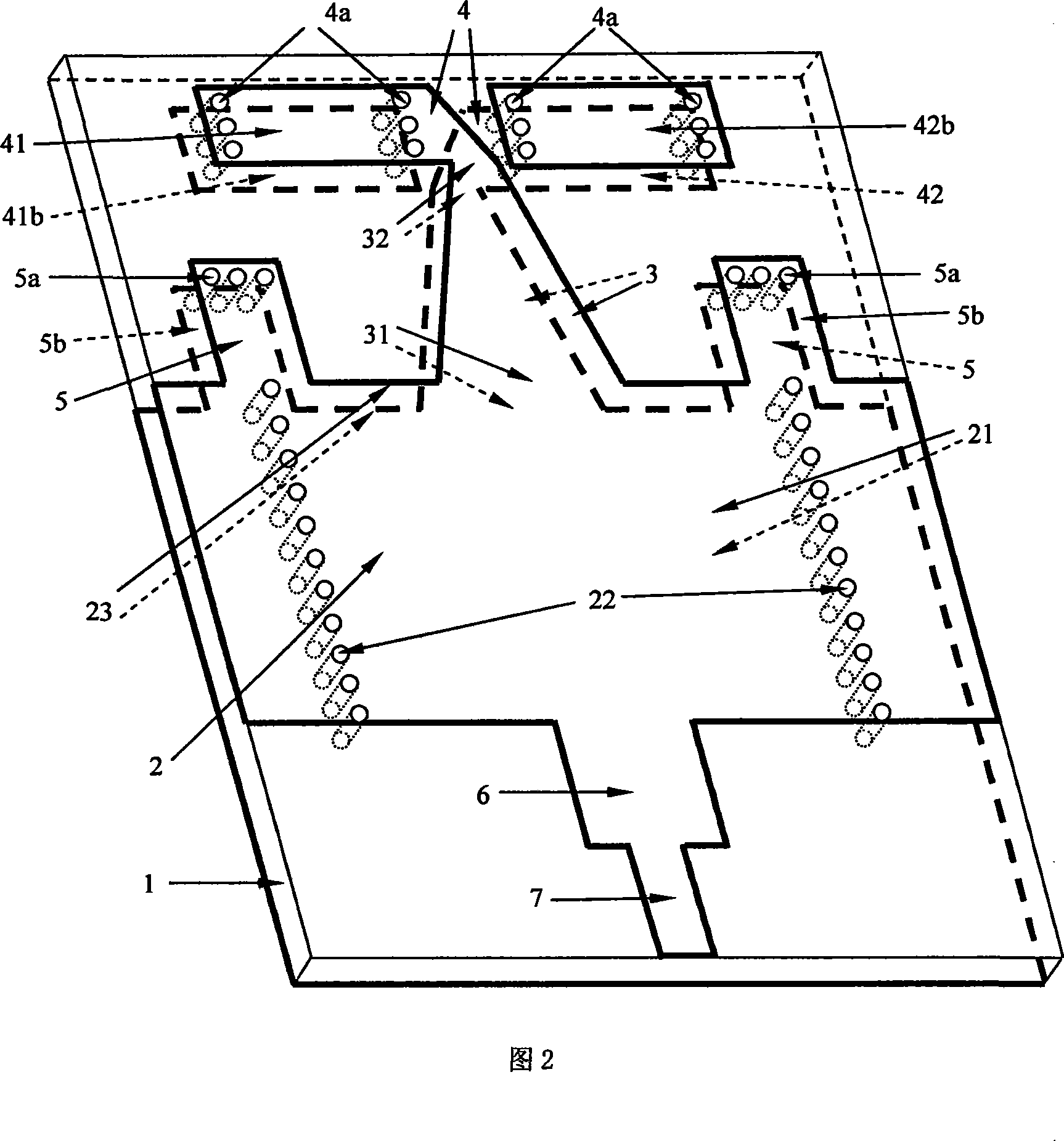
[0019] The structure of the antenna is shown in Figure 2, and the unit of size is mm. The size of the metal reflector is 150×150×4 (L×W×H), and a 43×1 slot is opened on the reflector to let the dielectric substrate with the substrate integrated waveguide and the printed antenna pass through. The size of the substrate in this embodiment is 43×44×1. One side of the reflector is the antenna radiating outward, and the other side is the SIW and the transition switch connected with the circuit. The gap is located at the SIW, so that the purpose of sealing and isolation can be achieved, and the short circuit of the radio frequency signal will not be caused because the gap on the metal reflector is connected to the metal on the upper and lower sides of the substrate.
Embodiment 2
[0020] Embodiment 2 A printed antenna array fed by a waveguide is integrated into a substrate that realizes sealing connection with a circuit shielding box.
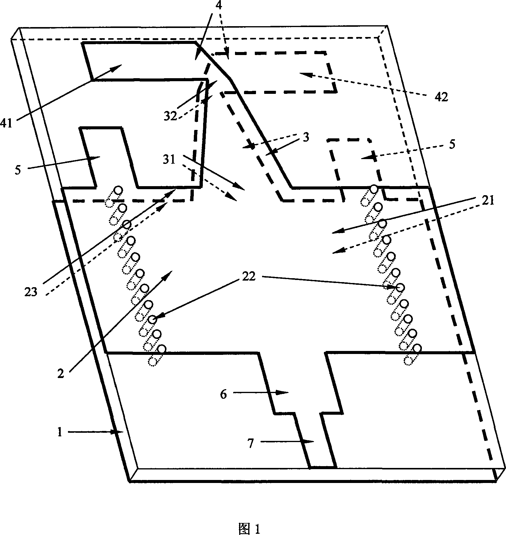
[0021] An antenna array structure in which the printed antenna fed by the substrate integrated waveguide is sealed and connected to the circuit inside the circuit shielding box through the gap on the reflector and the shielding box wall. An example is an 8×8 array, and each antenna board is processed with 8 substrate-integrated waveguide-fed printed antenna units arranged in the horizontal direction (represented by the structure in Figure 1 in the schematic diagram for the convenience of drawing) as shown in Figure 1 or Figure 2, each unit is formed by the SIW segment through the reflector and The gaps on the circuit box shell are connected to the corresponding circuits inside the circuit box. There are 8 layers of such circuit boxes and antenna boards arranged vertically to form an 8×8 array. Since the gap of each layer...
PUM
 Abstract
Description
Claims
Application Information
 - R&D Engineer
- R&D Manager
- IP Professional
- Industry Leading Data Capabilities
- Powerful AI technology
- Patent DNA Extraction
Browse by: Latest US Patents, China's latest patents, Technical Efficacy Thesaurus, Application Domain, Technology Topic, Popular Technical Reports.
© 2024 PatSnap. All rights reserved.Legal|Privacy policy|Modern Slavery Act Transparency Statement|Sitemap|About US| Contact US: help@patsnap.com


