
Manufacturing method of semiconductor device

A manufacturing method and semiconductor technology, applied in semiconductor/solid-state device manufacturing, semiconductor devices, electric solid-state devices, etc., can solve problems such as voids, abnormal growth of materials, and reduced productivity, and achieve high film thickness uniformity.

Inactive Publication Date: 2007-11-21
SANYO ELECTRIC CO LTD
View PDF1 Cites 29 Cited by
  • Summary
  • Abstract
  • Description
  • Claims
  • Application Information

AI Technical Summary

Problems solved by technology

In this way, the material (such as copper or aluminum alloy) of the penetrating electrode 106 will grow abnormally at the sharp portion 107, and there is a problem that an abnormally grown portion 108 as shown in FIG. 15B is generated.
In addition, when the abnormal growth portion 108 grows further, since it is connected to the material of the opposite via electrode, an appropriate plating layer cannot be formed, and there is a problem that the via electrode 106 is disconnected or a void is generated in the via electrode 106.
[0012] In addition, in the Bosch process, the generation of the rough shape 102 can be suppressed by slowing down the etching rate, but there is a problem that the productivity is significantly reduced

Method used


Image

  • Manufacturing method of semiconductor device
  • Manufacturing method of semiconductor device
  • Manufacturing method of semiconductor device

Examples


Embodiment Construction

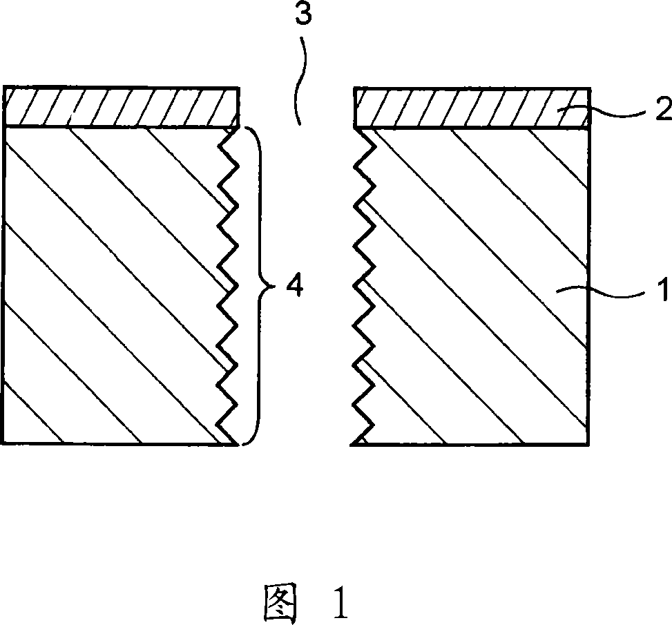
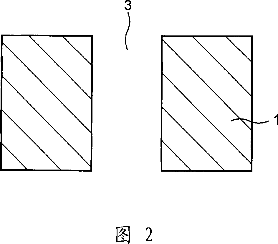
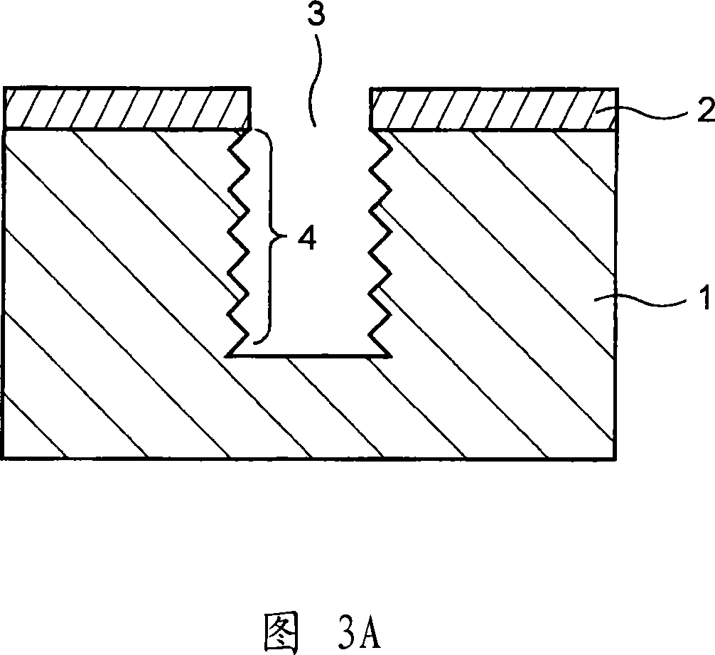
[0035] Next, embodiments of the present invention will be described with reference to the drawings. 1 to 3 are cross-sectional views illustrating a method of manufacturing a semiconductor device according to a first embodiment of the present invention.

[0036] First, as shown in FIG. 1 , a semiconductor substrate 1 on which an electronic device (not shown) is formed on the surface is prepared. Next, a mask layer 2 is selectively formed on the back surface of the semiconductor substrate 1 . The mask layer 2 is a layer used as a mask for forming the via hole 3, and its material is not particularly limited as long as it has this function. Therefore, the mask layer 2 may be an insulating film such as a silicon oxide film or a silicon nitride film, or may be a resist layer.

[0037] Next, a predetermined region of the semiconductor substrate 1 is etched by a Bosch process using the mask layer 2 as a mask. Specifically, for example, using an ICP (Inductively Coupled Plasma: Indu...


PUM


Abstract

This invention is directed to form a homogeneous film (12) in a via hole formed in a semiconductor device using Bosch process. The via hole (12) that penetrates through a predetermined region in a semiconductor substrate (5) is formed by etching the semiconductor substrate (5) from one of its surface to the other by the Bosch process using a mask layer (11) as a mask. Next, the mask layer (11) is removed. Then, scallops (13) are removed by dry etching to flatten a sidewall of the via hole (12). Following the above, an insulation film, a barrier layer and the like are formed homogeneously in the via hole (12).

Description

technical field [0001] The present invention relates to a method of manufacturing a semiconductor device, and more particularly, to a method of manufacturing a semiconductor device having an opening in a direction from one surface to the other of a semiconductor substrate. Background technique [0002] Conventionally, a process has been performed in which a via hole (opening) penetrating from one side of a semiconductor substrate to the other side is provided, and a conductive material (a metal such as aluminum, copper, tungsten, or titanium tungsten) is formed as a wiring in the via hole. , so that the conductors provided on the respective main surfaces are electrically connected. [0003] Also, a Bosch process is known as a method for forming such via holes. The Bosch process is a process in which a semiconductor substrate is etched deeply in a vertical direction by periodically repeating a plasma etching process and a plasma deposition process. The plasma etching proces...

Claims


Application Information

Patent Timeline
Patent Type & Authority Applications(China)
IPC IPC(8): H01L21/02H01L21/306H01L21/28H01L21/60
CPCH01L21/76898H01L21/30655H01L2924/0002H01L2224/02372H01L2224/05548H01L21/28H01L2924/00
Inventor 铃木彰关克行龟山工次郎及川贵弘
Owner SANYO ELECTRIC CO LTD
Learn More