


Quick Research
Generate reliable direction feasibility study reports for your R&D in just a few steps.

Technical Q&A
Discover and master advanced knowledge NOW. Basics, ideas, possibilities, all at once.

Find Solutions
As an expert in R&D theories, this can generate solutions to your technical problems instantly.

Evaluate Feasibility
Analyze your overall solution with one click, know your potential R&D risks in advance.

Monitor Landscape
Get weekly tech updates, stay abreast of the latest tech innovations and key insights.
Centrifugal fan
A technology of centrifugal fans and fan blades, which is applied to non-variable pumps, non-volume pumps, components of pumping devices for elastic fluids, etc., can solve annoying narrow-band noise and other problems, and reduce narrow-band noise. noise effect
- Summary
- Abstract
- Description
- Claims
- Application Information
AI Technical Summary
Problems solved by technology
Method used
Image

Examples
Embodiment Construction
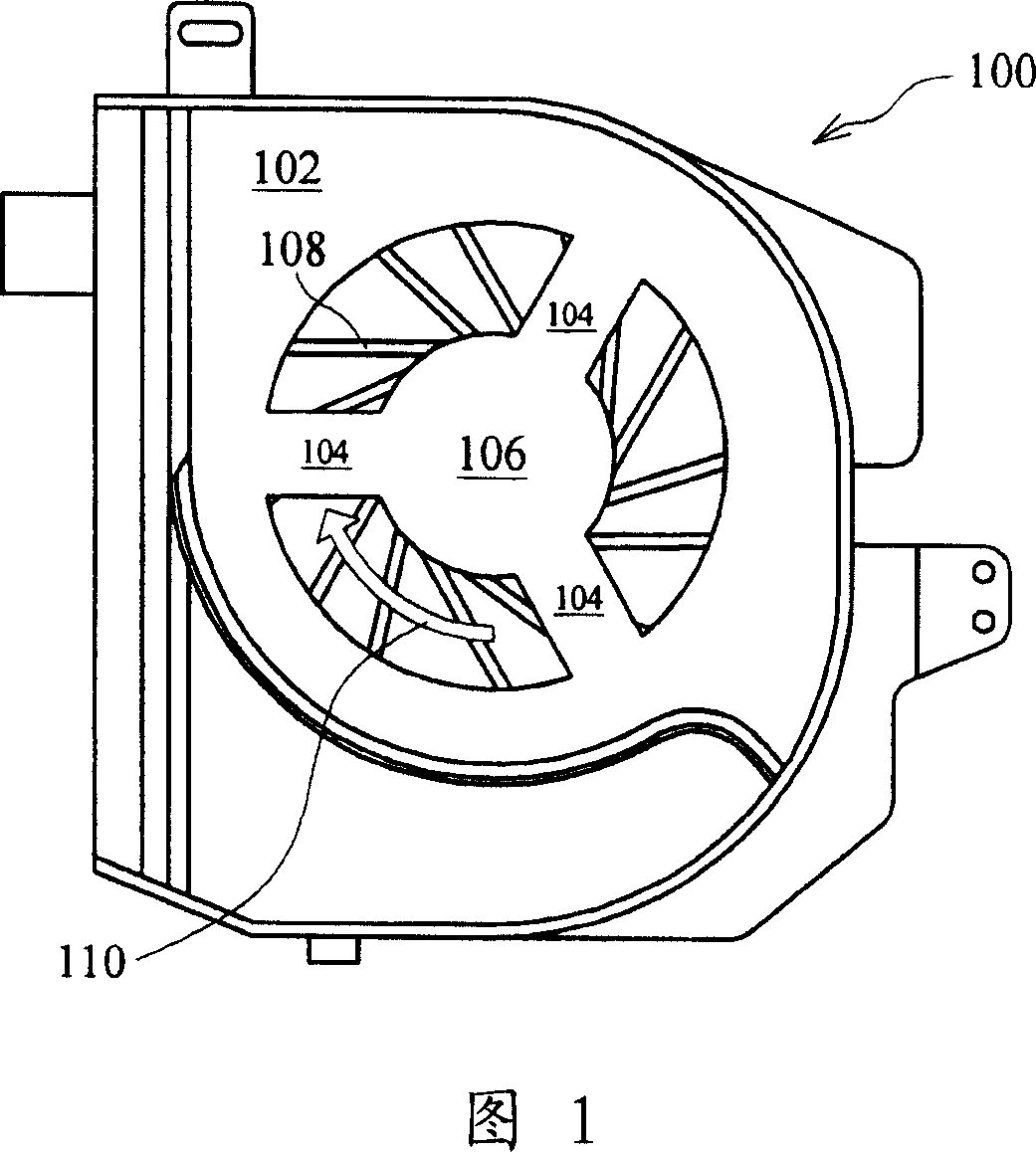
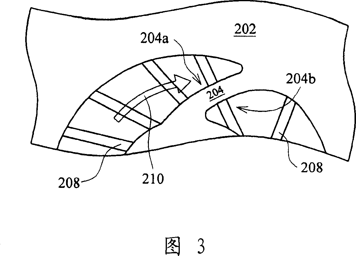
[0024] As mentioned above, the present invention provides a centrifugal fan, the outline of the bracket on the volute casing is formed by the involute obtained by taking the motor bearing base as the base circle. The blades of the fan adopt a backswept design, and the blades are vertically intersected with the outline of the bracket, so that the impact of the traction airflow caused by the blade rotation and the bracket is reduced, thereby reducing the narrow-frequency noise caused by it. The structure of the centrifugal fan will be described in detail below in conjunction with preferred embodiments.
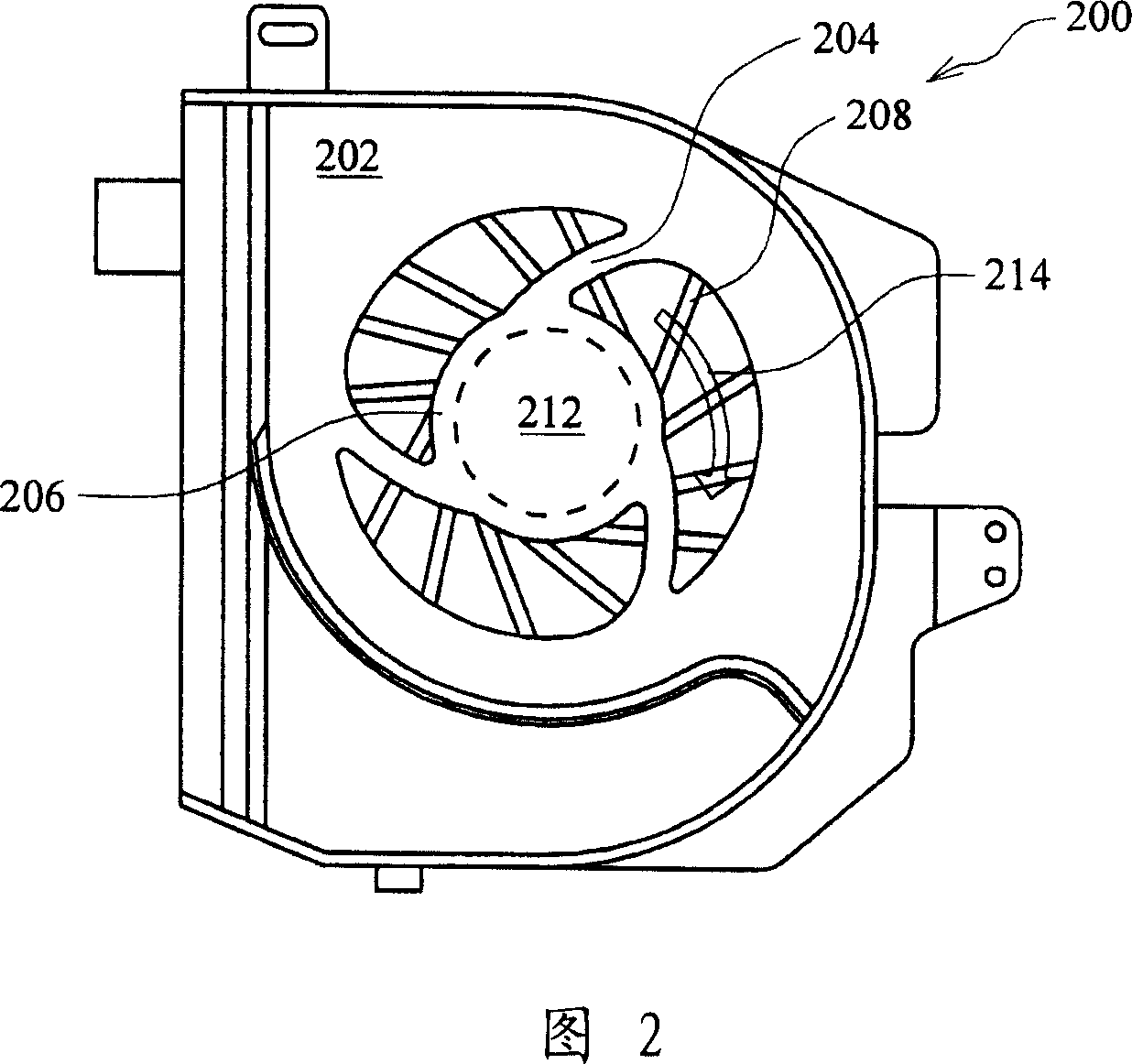
[0025] Please refer to FIG. 2 , which shows a frame structure diagram of a centrifugal fan according to a preferred embodiment of the present invention. The volute casing 202 of the centrifugal fan 200 includes a driving device 212 (such as a motor) and a fan blade 108 . The driving device 212 is fixed on the back side of the bearing seat 106 in the figure (indicated by a dotte...
PUM
 Abstract
Description
Claims
Application Information
 - R&D Engineer
- R&D Manager
- IP Professional
- Industry Leading Data Capabilities
- Powerful AI technology
- Patent DNA Extraction
Browse by: Latest US Patents, China's latest patents, Technical Efficacy Thesaurus, Application Domain, Technology Topic, Popular Technical Reports.
© 2024 PatSnap. All rights reserved.Legal|Privacy policy|Modern Slavery Act Transparency Statement|Sitemap|About US| Contact US: help@patsnap.com