Distributed diplexer

A frequency band and circuit technology, applied in the field of multi-band RF circuits, can solve the problems of low tolerance, small flexibility or selection of different modules, complex circuit manufacturing, etc., to increase battery life, reduce transmission loss, and improve open circuit characteristics. Effect

Inactive Publication Date: 2007-11-07
NXP BV
View PDF2 Cites 13 Cited by
  • Summary
  • Abstract
  • Description
  • Claims
  • Application Information

AI Technical Summary

Problems solved by technology

This can result in smaller antenna sizes for applications such as mobile handsets
However, this circuit is very complex to manufacture because the layout of the metal lines and antenna coupling requires careful design and will typically have small tolerance...

Method used


Image

  • Distributed diplexer
  • Distributed diplexer
  • Distributed diplexer

Examples


Embodiment Construction

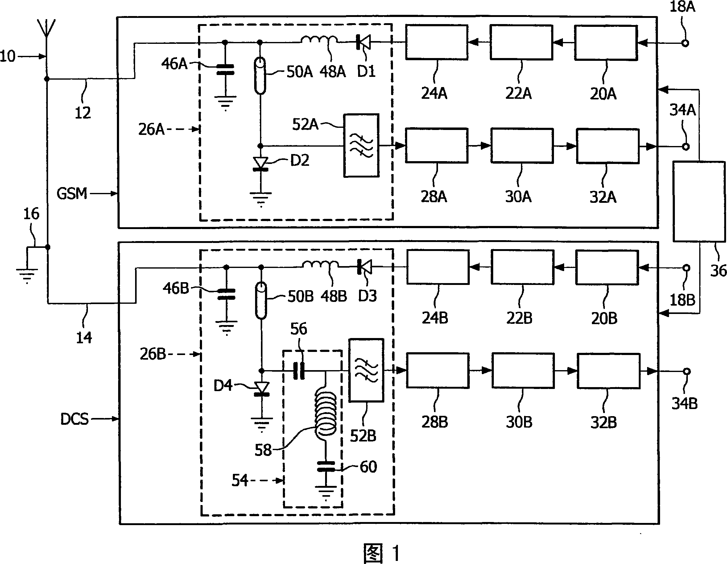
[0030] As an introduction to the present invention, an existing wireless terminal is described with reference to FIG. 1 . Embodiments may use many of the parts shown in this figure. This wireless terminal comprises a Planar Inverted-F Antenna (PIFA) 10 having feeders 12 and 14 connected respectively to a GSM transceiver operating on the 880 to 960 MHz band, and to a DCS operating on the 1710 to 1880 MHz band. transceiver. Between the feed lines 12 and 14 an earth line 16 is provided. Since the structures of GSM and DCS transceivers are generally the same, and the corresponding stages will be marked with suffixes A and B respectively, and for the sake of brevity, only the GSM transceiver will be described. The transmitter part of the GSM transceiver comprises a signal input 18A connected to an input signal processing stage 20A. Stage 20A is connected to modulator 22A, which provides the modulated signal to transmitter stage 24A, which includes an upconverter, a power amplifi...


PUM


Abstract

A multi-band RF circuit has receive paths for two or more bands, and transmit paths, a bidirectional one-in multiple-out transmission line junction (100) for combining the paths for coupling to an antenna. A switch combines transmit and receive paths, and a receive path circuit (110, 150, 160, 230, 240) is arranged to pass signals of its band, and appear open circuit to signals of the other bands. This means the combiner no longer needs to cut off the receive paths when they are not used. This can reduce components and thus reduce losses in the transmit paths for longer battery life or greater transmit range. A band filter (SAW) and a complementary circuit can achieve the open circuit. The bands can include GSM and GPS bands, the circuits can be used in tri band mobile handsets and handsets for future 3G bands, or base stations.

Description

technical field [0001] The invention relates to: a multiband RF circuit, a device having such a circuit connected to an antenna, and a mobile device or a fixed base station having such a circuit. Background technique [0002] It is known to provide a handset with an RF circuit for multiple frequency bands (usually two or three frequency bands). Duplexers (also known as diplexers or multiplexers) can be used to connect RF circuits of different frequency bands with antennas. This effectively switches one or more transmit paths to the antenna and separates the receive path from the transmit path. As shown in Figure 1, a switch is provided for each frequency band to separate the transmit and receive paths. This duplexer usually consists of passive components and introduces some power loss in the transmit path. There are also losses due to the need to share antennas and matching circuits between two or more frequency bands, which means that these parts cannot be optimized for ...

Claims


Application Information

Patent Timeline
IPC IPC(8): H04B1/40
CPCH04B1/0057H04B1/406
Inventor 凯文·R·博伊尔
Owner NXP BV
Why Eureka
Try Eureka