
Optical source concentrated wave division multiplexing passive optical network for simultaneously generating the DPSK and OOK signals

A technology of passive optical network and wavelength division multiplexing, which is applied in the direction of wavelength division multiplexing system, selection device of multiplexing system, phase modulation carrier system, etc., can solve the problem of lack of high efficiency and increase the cost of optical fiber wireless communication system 、 Failure to realize downlink signal wavelength reuse and other issues

Inactive Publication Date: 2007-10-17
HUNAN UNIV
View PDF0 Cites 9 Cited by
  • Summary
  • Abstract
  • Description
  • Claims
  • Application Information

AI Technical Summary

Problems solved by technology

However, the method and receiving demodulation device of the passive optical network wavelength division multiplexing system proposed at present are complex, lack of efficiency, and the wavelength reuse of the downlink signal is not realized at the uplink end, thus increasing the cost of the optical fiber wireless communication system. cost

Method used


Image

  • Optical source concentrated wave division multiplexing passive optical network for simultaneously generating the DPSK and OOK signals
  • Optical source concentrated wave division multiplexing passive optical network for simultaneously generating the DPSK and OOK signals
  • Optical source concentrated wave division multiplexing passive optical network for simultaneously generating the DPSK and OOK signals

Examples


Embodiment Construction

[0059] The present invention will be described in detail below in conjunction with specific experimental examples and accompanying drawings.

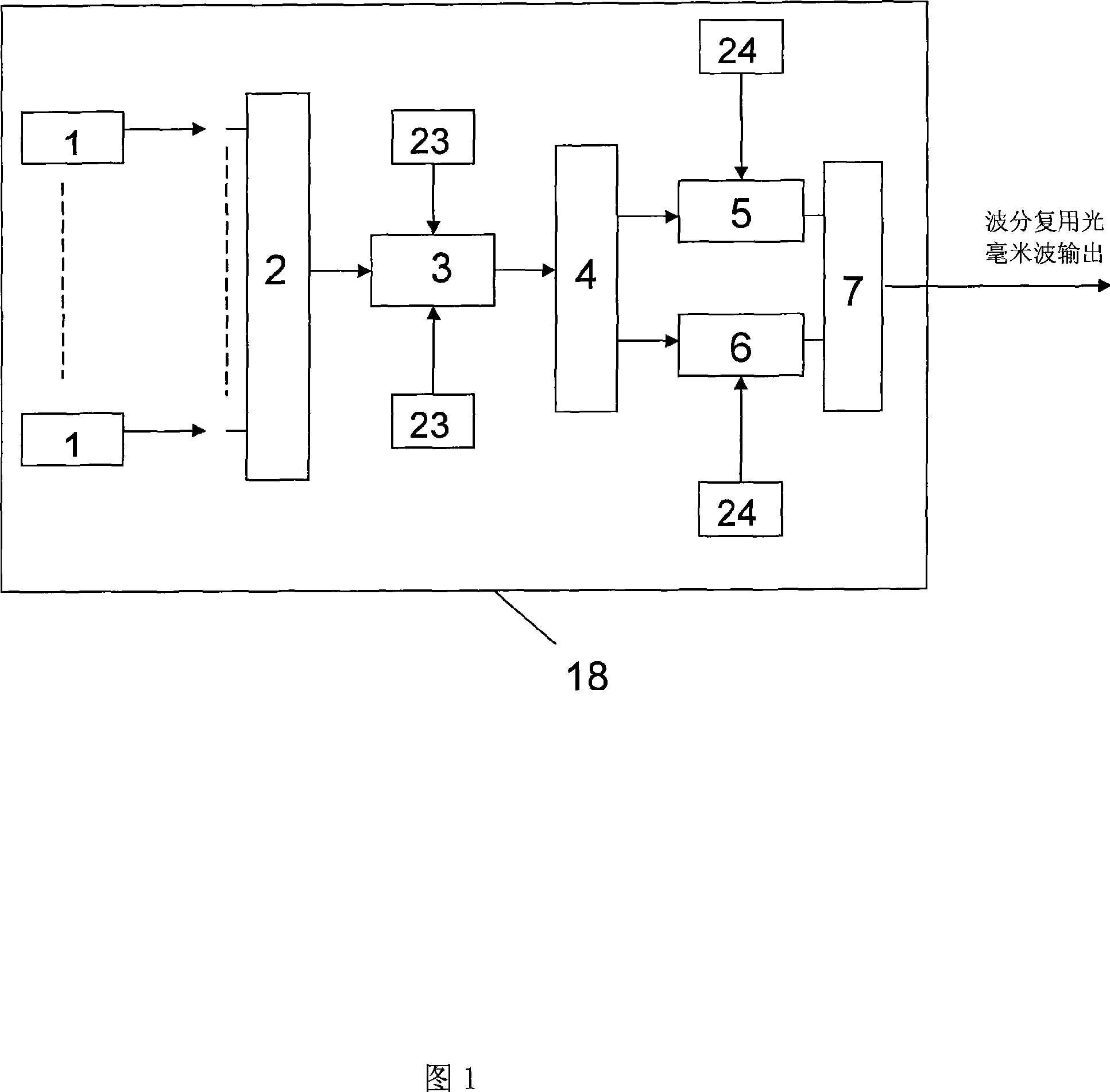
[0060] As shown in Figure 1, it is a passive optical network wavelength division multiplexing system device that simultaneously generates DPSK and OOK modulation signals, which includes:

[0061] Multiple distributed feedback lasers 1 to generate multiple optical carrier signals;

[0062] The optical wavelength division multiplexer 2 realizes the wavelength division multiplexing of multiple optical carrier signals;

[0063] The optical intensity modulator 3 realizes the intensity modulation of the carrier suppression separation of the multiplexed optical signal;

[0064] The optical interleaver 4 separates the 2N order optical carrier signal;

[0065] Optical intensity modulator 5, sampling the OOK modulation mode to modulate the data signal onto the optical carrier signal;

[0066] Optical phase modulator 6, sampling the DPSK modula...


PUM


Abstract

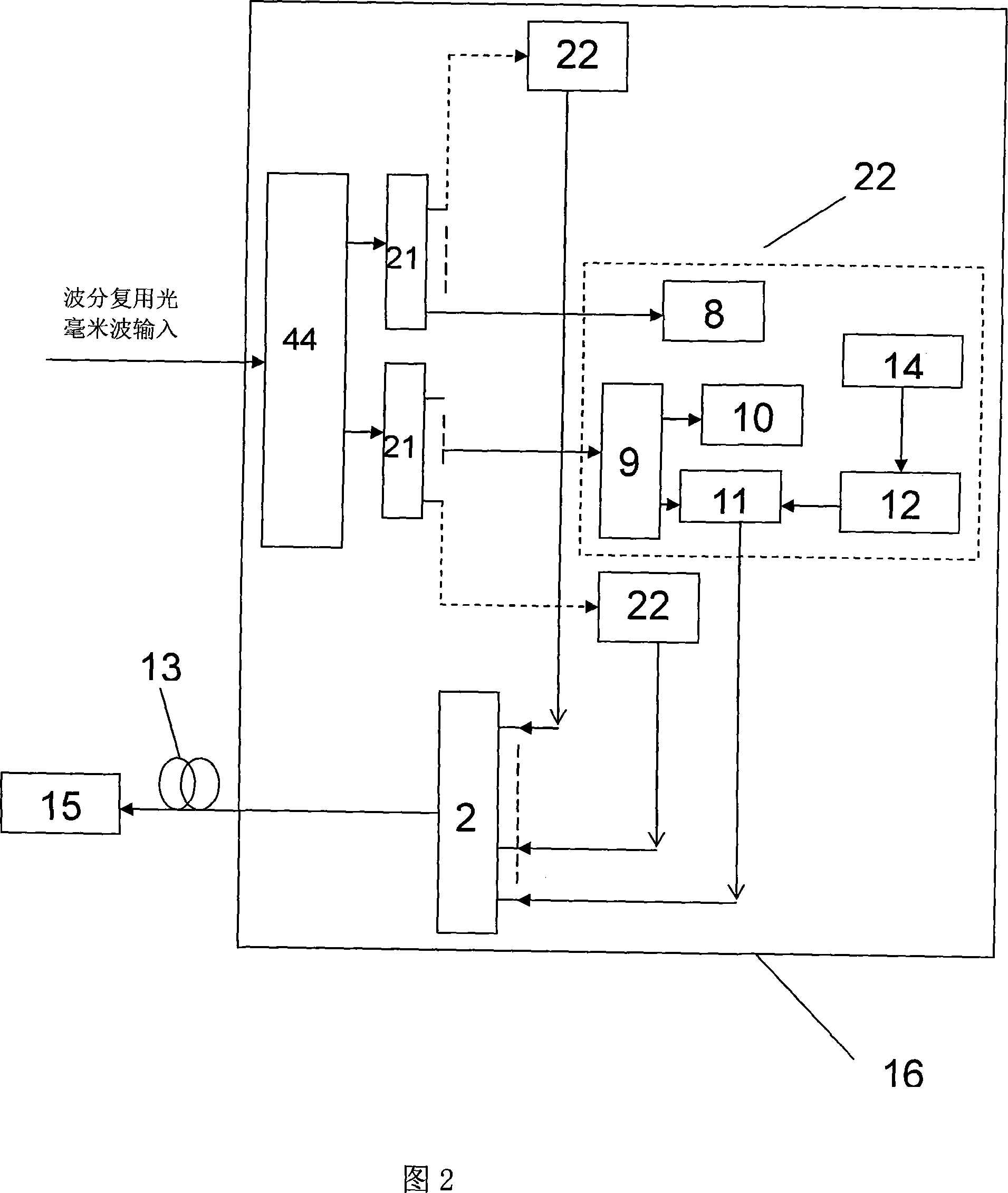
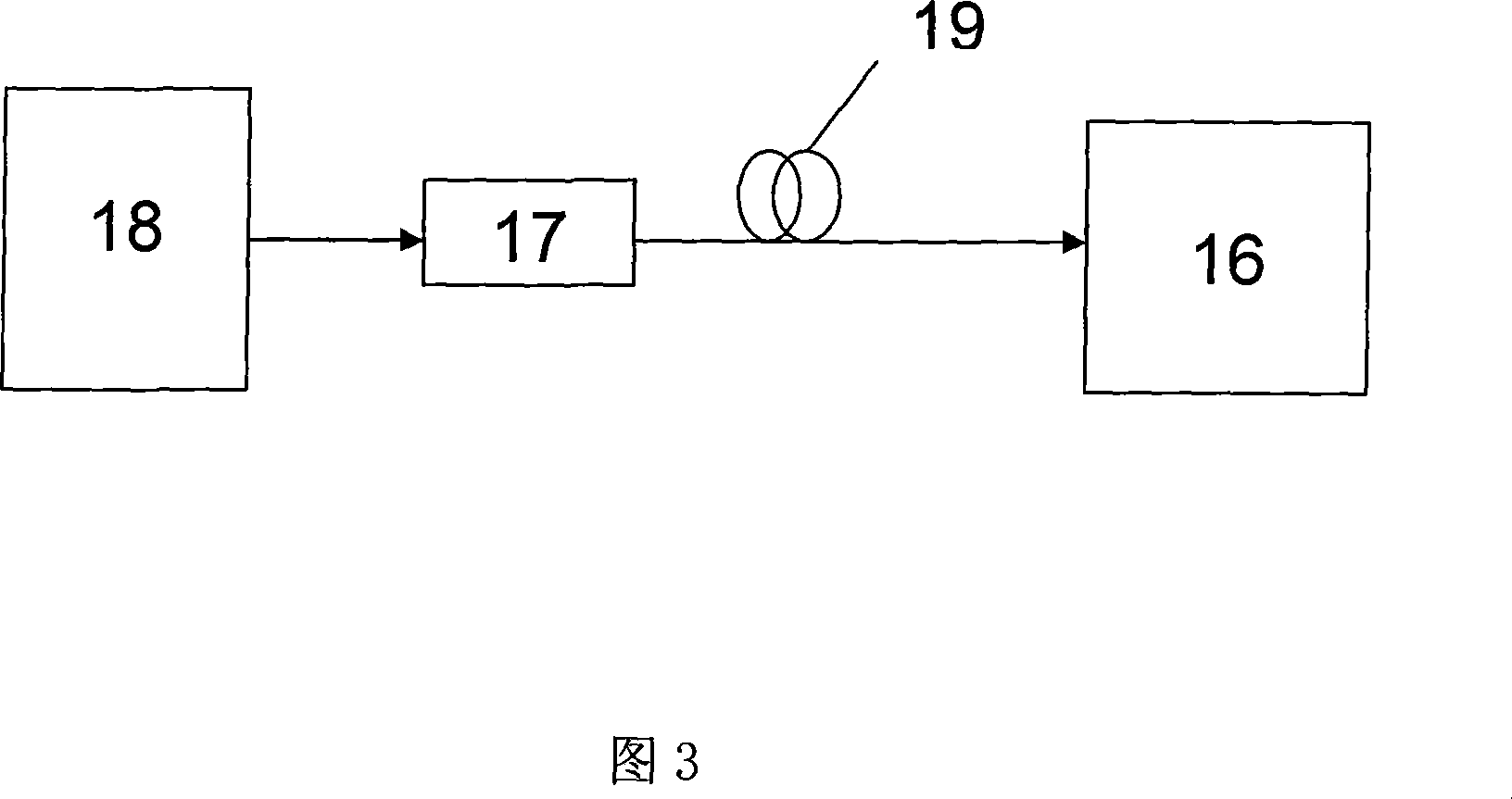
The present invention discloses a wavelength division multiplex passive light network system that generates DPSK and OOK signals at the same time and centralizing the light sources in the field of wavelength division multiplexing passive optical network system (WDM-PON) and the technology of light network communication system. In the passive light network downlink center station, the optical lineterminal (OLT) is composed of N paths of light sources of distributed feedback laser and the N paths of light sources passes through a double-arm intensity modulator after passing through a wavelength division multiplexer to realize the optical carrier suppressing separation (OCSS) for forming nth-order optical signals; then the signals passes through an interleaver (IL) and the separated signalsare performed on-off keying (OOK) modulation and differential phase shift keying (DPSK) modulation; and the modulated signals of two paths are transmitted to the remote nodes of the passive light network from the optical fiber after being coupled. In the remote nodes, the downlink signals transmitted through a long-distance fiber line are separated through another interleaver (IL) and the intensity modulation signals are separated from the phase modulation signals; the intensity modulation signals and the phase modulation signals are routed through two demultiplexers (DeMux) to the corresponding passive optical network unit (ONU); in the passive optical network unit (ONU), 3R light receiving unit will detect the modulated on-off keying (OOK) modulation signals directly; the differential phase shift keying (DPSK) modulation signals are divided into two paths by the optical branch divider: one path of signals are modulated out the intensity signals directly through the MZ wave guide time delay interferometer; the other path of signals are modulated through reflecting type semiconductor optical amplifier (RSOA) for the recycle of wavelength.

Description

(1) Technical field [0001] The invention belongs to the technical field of passive optical network wavelength division multiplexing system (WDM-PON) and optical network communication system. (2) Background technology [0002] The development of optical communication technology mainly presents two directions: the backbone level is developing towards high-speed, large-capacity, and intelligent optical networks, and finally realizes all-optical networks; the access level is towards low-cost, integrated access, broadband, The development of fiber-based access network will eventually realize fiber-to-the-home and fiber-to-the-desktop. [0003] The development of passive optical networks is changing with each passing day. The more optical fibers are promoted to users, the more obvious the comprehensive advantages of passive optical access technology will be. The advantage of passive optical access technology in passive optical network is that it has the advantages of saving fiber...

Claims


Application Information

Patent Timeline
IPC IPC(8): H04J14/02H04L27/20H04B10/155H04Q11/00H04B10/548
Inventor 余建军陈林
Owner HUNAN UNIV
Learn More