Permanent magnet for motor, motor housing and motor device

A technology for permanent magnets and motors, applied in the field of permanent magnets, can solve problems such as poor corrosion resistance, difficulty in applying heat resistance, poor heat resistance of bisphenol A epoxy resin, etc.

Inactive Publication Date: 2007-10-03
AICHI STEEL
View PDF3 Cites 11 Cited by
  • Summary
  • Abstract
  • Description
  • Claims
  • Application Information

AI Technical Summary

Problems solved by technology

[0008] Because there is a coating treatment layer and an adhesive layer between the anisotropic rare earth bonded magnet that constitutes the electromagnetic circuit and the motor casing, an air gap will be generated in the electromagnetic circuit, so the anisotropic rare earth cannot be fully utilized. Potential Capabilities of Like Bonded Magnets
Thus affecting the characteristics of the motor using the magnet
[0009] Furthermore, bisphenol A type epoxy resin has poor heat resistance, and it will be difficult to apply to the automotive field with high heat resistance.
[0010] In addition, the coating of anisotropic rare-earth bonded magnets composed of bisphenol A type epoxy resin also uses the same epoxy resin, and its corrosion resistance in organic solvent media is poor.

Method used


Image

  • Permanent magnet for motor, motor housing and motor device
  • Permanent magnet for motor, motor housing and motor device
  • Permanent magnet for motor, motor housing and motor device

Examples


no. 1 Embodiment

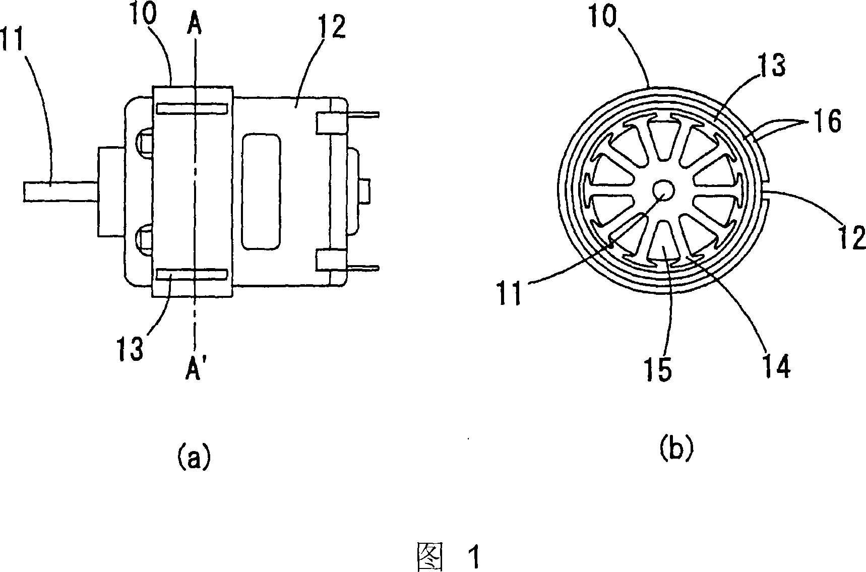
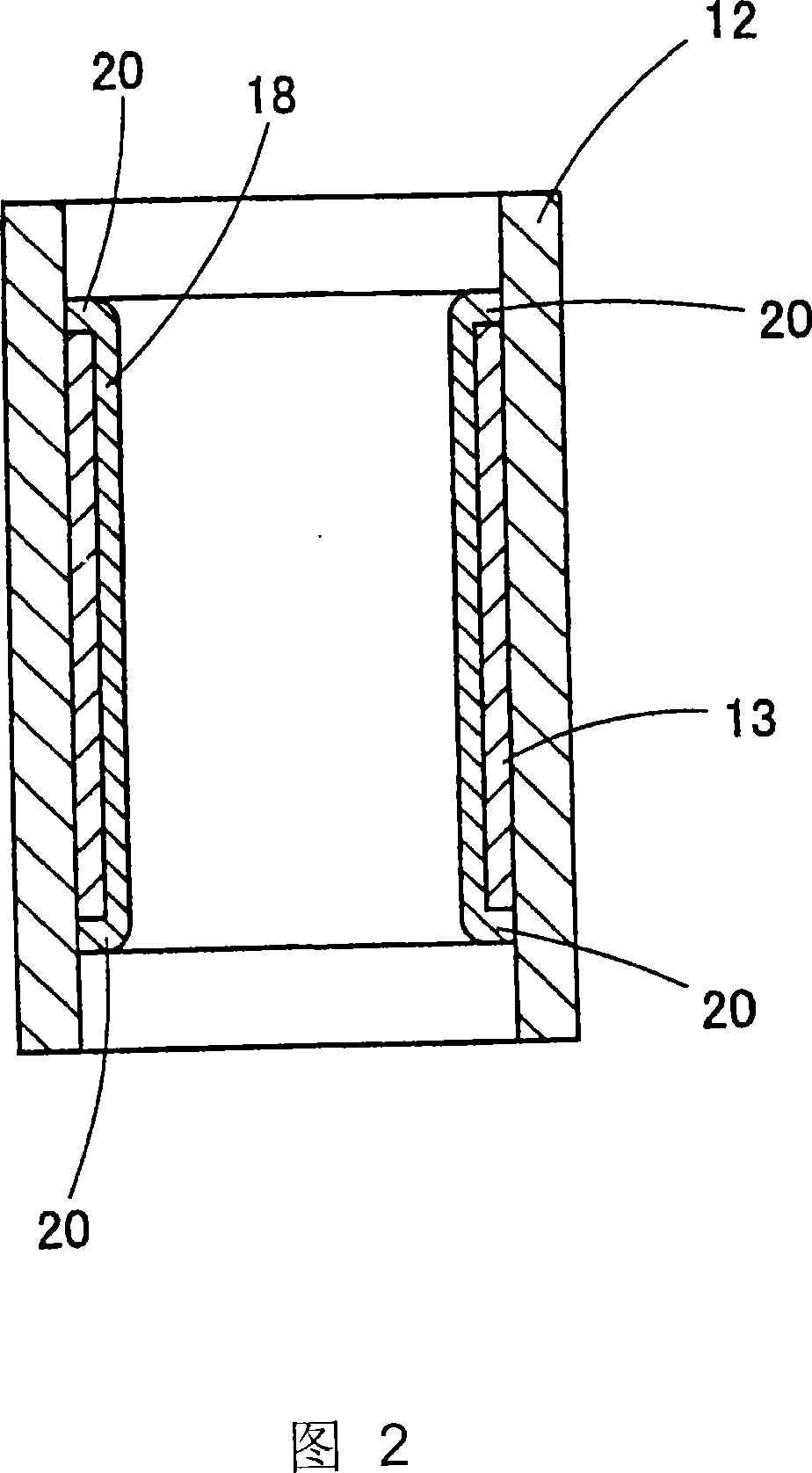
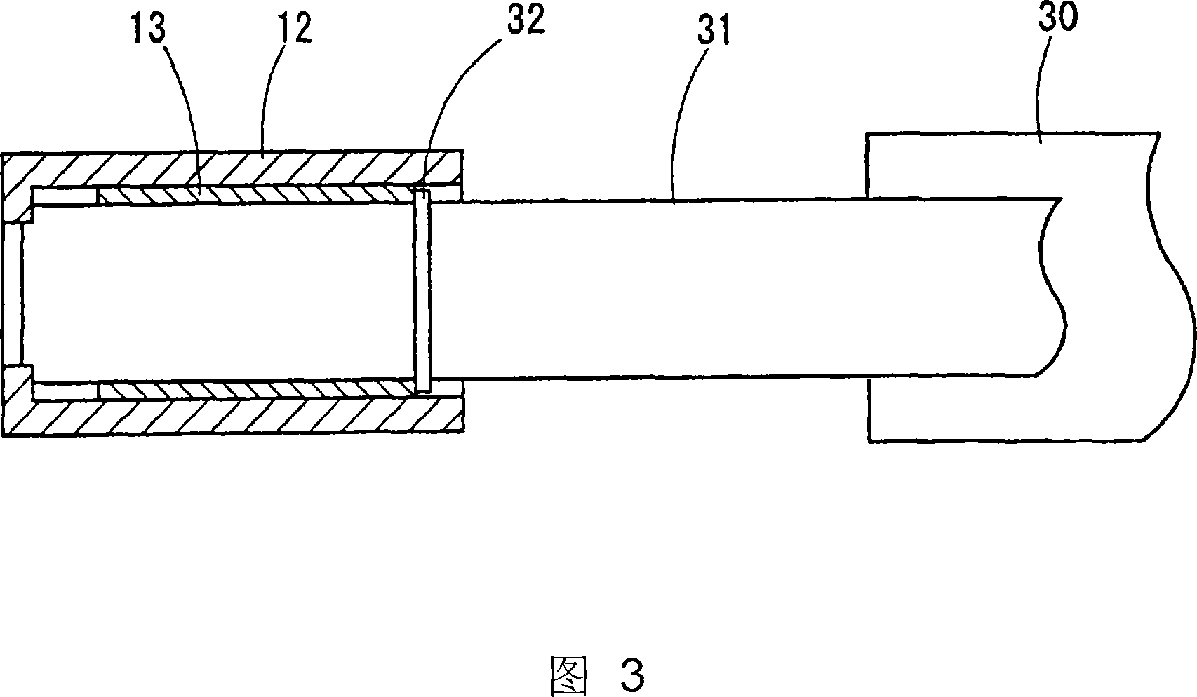
[0096] FIG. 1(a) and FIG. 1(b) show an example of the motor device according to this embodiment. Figure 1(a) is a side view, and Figure 1(b) is a cross-sectional view of AA'. Compared with conventional motor devices, the motor device shown in this embodiment has the characteristics of downsizing and high torque, and can prevent deterioration of motor characteristics over time when used in an organic solution. The motor device shown in this embodiment has the following configuration. An anisotropic rare-earth bonded magnet 13 having a hollow cylindrical shape as a permanent magnet is provided in the casing 12 and the inner peripheral portion of the casing 12; in addition, a rotor 14 forming an electromagnetic rotating body is provided in the central portion. A coil 15 is wound around the rotor 14, and a rotary shaft 11 protrudes from the center of the rotor 14; and an outer yoke 10 is provided for preventing loss of magnetic flux. Here, it should also be emphasized that the a...

experiment example

[0128] In the following, various characteristics of anisotropic rare earth bonded magnets are measured and analyzed.

[0129] The binder in the anisotropic rare earth bonded magnet of the present invention uses phenol novolac epoxy resin, while the binder in the previous bonded magnet uses bisphenol A epoxy resin. In this embodiment, firstly, the viscosity characteristics of phenol novolac epoxy resin and bisphenol A epoxy resin with respect to temperature change were measured and analyzed respectively. The result is shown in Figure 5. From the measured results, it can be seen that the minimum (low) value of the viscosity of the phenol novolac epoxy resin used in the present invention is one digit smaller than the minimum (low) value of the viscosity of the bisphenol A epoxy resin. Moreover, at this time, the temperature of phenol novolac epoxy resin is much lower than that of bisphenol A epoxy resin. If the magnetization and orientation treatment of the magnetic powder is c...


PUM

PropertyMeasurementUnit
magnetic lossaaaaaaaaaa
dimension changeaaaaaaaaaa

Abstract

To improve the resistance to an organic solvent and the deterioration with age of a motor device. A motor device, wherein an exiting magnet is formed with an anisotropic bonded magnet (13) in a hollow and cyrindrical form, and the bonded magnet (13) is forced into and held in a housing (12), wherein the bonded magnet (13) comprises an anisotropic bonded magnet in a hollow and cyrindrical form being prepared by kneading an anisotropic rare earth magnetic powder with a phenol-novolac type epoxy resin, followed by forming, and wherein the anisotropic bonded magnet (13) is forced into the housing (12) along the internal circumference thereof, and the exposed surface layer of the anisotropic rare earth bonded magnet having been forced into the housing is subjected to a penetration treatment (defined in the specification) with a polyamideimide based resin and is covered by a coating layer.

Description

technical field [0001] The present invention is a technical invention related to permanent magnets for motors, motor housings and motor devices containing permanent magnets. In particular, the permanent magnet of the present invention uses an anisotropic rare earth bonded magnet, which can realize miniaturization and high torque of the motor device, and the motor case and the motor device of the present invention have excellent heat resistance, At the same time, it can be used in the environment of organic solvents (including liquid state and gas state). For example, a fuel pump immersed in petroleum products such as gasoline and diesel for automobiles can use the motor casing and motor device of the present invention. technical background [0002] In recent years, in the field of electric motors, the performance of electric motors has been improved due to the use of anisotropic rare earth bonded magnets. However, the requirements for high performance and miniaturization o...

Claims


Application Information

Patent Timeline
Patent Type & Authority Applications(China)
IPC IPC(8): H01F7/02H01F41/02H01F1/08F02M37/10F04B9/00H02K23/04H02K1/17H01F1/053
CPCF02M37/10H01F1/0572H02K15/03F04D13/06H02K1/17H01F41/026H01F1/0578H01F1/0573H01F1/059F04D5/002
Inventor 本蔵義信松冈浩鹿野厚野口健儿御手洗浩成菅悟
Owner AICHI STEEL
Why Eureka
Try Eureka