Anti-wedging type high speed mixer drum

A technology of high-speed mixing and stirring shafts, which is applied in the direction of cement mixing devices, clay preparation devices, chemical instruments and methods, etc., can solve problems such as lowering product quality, improper crushing of stones, and harsh working conditions, so as to reduce power consumption and shorten Stirring time, the effect of avoiding wedge phenomenon

Inactive Publication Date: 2010-05-12
ZHENJIANG HUACHEN HUATONG ROAD MASCH CO LTD
View PDF3 Cites 0 Cited by
  • Summary
  • Abstract
  • Description
  • Claims
  • Application Information

AI Technical Summary

Problems solved by technology

[0003] Conventional tests have shown that when the speed of the blade tip is greater than 2.7m / s, too much debris will be wedged in the gap between the bottom of the cylinder 1 and the blade end, that is, as shown in the figure figure 1 And attached figure 2 As shown, due to the paddle 3', the center of rotation of the stirring shaft 2' coincides with the cylinder body 1' and the center of the arc of the liner. The gap between the blade and the liner is constant. When the diameter of the stone is equal to the gap between the paddle liner, stone wedging is prone to occur. At this time, the working conditions of the blade and the liner are very bad, and the result is often It is the paddle liner that crushes the stone, which affects the gradation of the finished material and reduces the product quality, or the paddle entrains the stone and passes through the arc area forcibly, causing severe wear to the paddle liner, or the first two Combined movement, resulting in huge power consumption, increased wear on mixing bowl parts, and undue crushing of stone
Affect the normal working performance of the equipment
For this reason, the existing equipment of this type generally controls the speed of the tip of the blade to ≤2.7m / s, which limits the improvement of the working efficiency and production capacity of the equipment.

Method used


Image

  • Anti-wedging type high speed mixer drum
  • Anti-wedging type high speed mixer drum
  • Anti-wedging type high speed mixer drum

Examples


Embodiment Construction

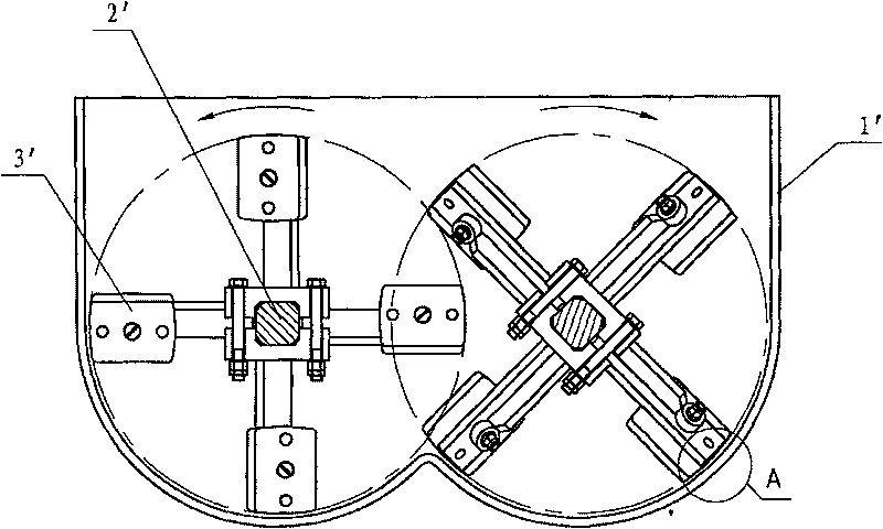
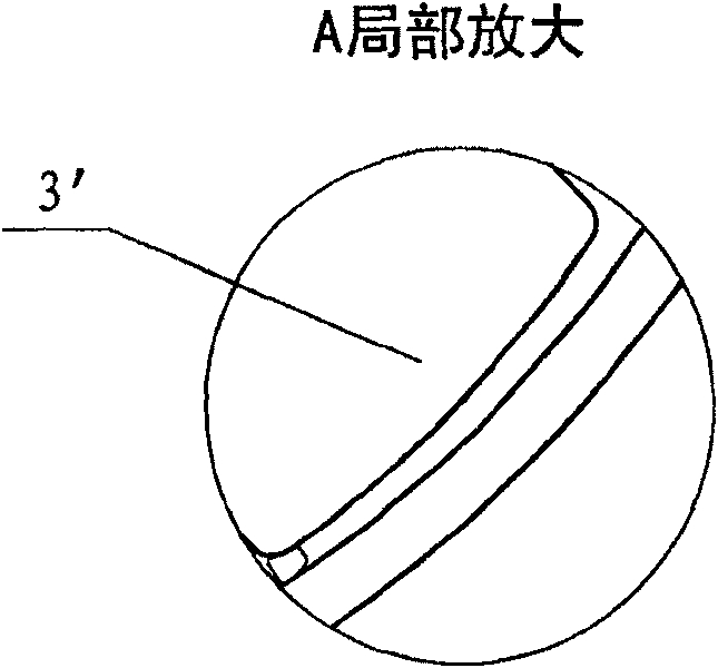
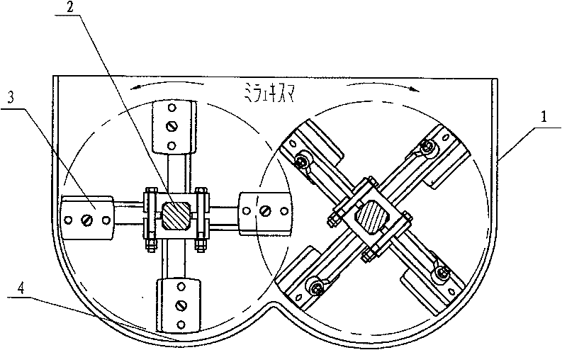
[0011] Such as image 3 , Figure 4 As shown, a stirring shaft 2 is installed in the cylinder body 1 of the anti-wedge extrusion high-speed mixing cylinder, and a paddle 3 is installed on the stirring shaft. Wear-resistant liners are distributed on the arc-shaped bottom surface 4 of the cylinder body, and the stirring shaft and the paddle There is an eccentric distance between the center of rotation of the blade and the center of the arc on the bottom surface of the cylinder, so that the distance between the running track of the end of the blade and the wear-resistant liner increases gradually in the direction of the blade. Such as Figure 4 As shown, the eccentric distance may include a lateral eccentricity x and a vertical eccentricity y.


PUM


Abstract

A high-speed asphalt agitator without jam has an agitating tank with antiwear liner on its arc bottom, and two agitating axle with blades. It features that the rotational center of said agitating axleand blades and the circular center of said arc bottom are eccentric, so the distance between the tracing of blades and the antiwear liner is gradually increased, resulting in no jam.

Description

technical field [0001] The invention belongs to road construction machinery, and relates to the structure of a paddle-type mixing cylinder of asphalt mixing equipment, in particular to an anti-wedge extrusion mixing cylinder. Background technique [0002] Paddle mixing tank is the main device in the preparation process of asphalt mixture mixing equipment. In the mixing tank, the gravel material, mineral powder and asphalt weighed according to a certain mixing ratio are evenly mixed into the required finished asphalt concrete mixture. The paddle type mixing cylinder mainly includes a cylinder body and a pair of stirring shafts installed side by side in the cylinder body. The paddles for stirring are installed on the stirring shafts, and the arc-shaped bottom surface of the cylinder body is provided with a wear-resistant liner. When the mixing tank is working, the paddles buried in the bottom of the mixing tank in the mixture make the mixture move longitudinally and laterally...

Claims


Application Information

Patent Timeline
Patent Type & Authority Patents(China)
IPC IPC(8): B28C5/16
Inventor 肖羽宇徐宝元杨宝林崔亮林卫军
Owner ZHENJIANG HUACHEN HUATONG ROAD MASCH CO LTD
Why Eureka
Try Eureka