
Card adapter device

A technology of card adapters and contact terminals, which is applied in the direction of coupling devices, cooperative devices, instruments, etc., can solve the problems of device reliability decline, spring characteristic deterioration, and inability to ensure contact pressure, etc., and achieve high reliability and good spring characteristics , to achieve the effect of miniaturization

Inactive Publication Date: 2007-09-19
ALPS ALPINE CO LTD
View PDF1 Cites 0 Cited by
  • Summary
  • Abstract
  • Description
  • Claims
  • Application Information

AI Technical Summary

Problems solved by technology

However, if such a structure is formed, the spring characteristics of these card contact terminals will be deteriorated along with the shortening of the length dimension of each card contact terminal, and good contact pressure cannot be ensured between these card contact terminals and the card, resulting in device failure. The problem of reduced reliability

Method used


Image

  • Card adapter device
  • Card adapter device
  • Card adapter device

Examples


Embodiment Construction

[0031] The best mode for carrying out the card adapter device of the present invention will be described below with reference to the drawings.

[0032] (Structure of this embodiment)

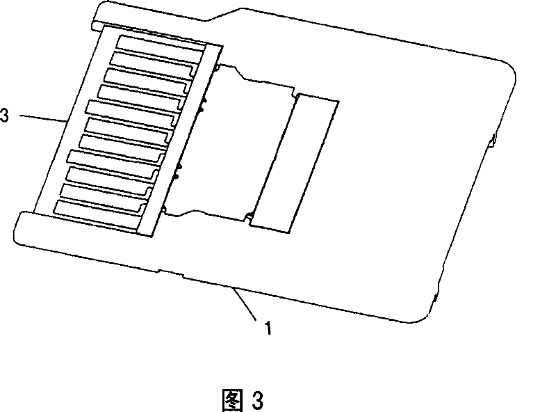
[0033] 1 is an exploded perspective view showing one embodiment of a card adapter device according to the present invention, FIG. 2 is a perspective view of this embodiment, and FIG. 3 is a perspective view showing the rear side of this embodiment.

[0034] As shown in FIGS. 1 to 3 , the present embodiment includes a frame body composed of a lower frame body 1 forming an outer casing and an upper frame body 2 joined to the lower frame body 1 . The terminal unit 3 is accommodated between the two. In addition, a thin metal plate 4 that closes the opening 2 a of the upper housing 2 is provided, and the thin plate 4 is disposed above the terminal unit 3 .

[0035] 4 is a plan view showing the state without the upper frame and the thin plate from this embodiment, FIG. 5 is a rear view of the embodi...


PUM


Abstract

PROBLEM TO BE SOLVED: To bring a contact part of each card contact terminal touching a card close to each external connection terminal and to secure good spring characteristics of each card contact terminal. ŽSOLUTION: This card adapter device is provided with a card mounting part 9, a plurality of card contact terminals 6 each having a contact part 6a capable of touching the card 13 attached to the card mounting part 9, and a plurality of external contact terminals 7 arranged on the front side of these card contact terminals 6 and connectable with an external apparatus. Each of the card contact terminals 6 is formed into a cantilever shape, in which the contact part 6a is positioned on the external contact terminal 7 side individually, and provided with a plurality of conduction parts 8 protruded from the base parts of the respective card contact terminals 6 for electrically connecting the card contact terminals 6 to the corresponding external contact terminals 7 respectively. Ž

Description

technical field [0001] The present invention relates to a card adapter device suitable for miniaturization. Background technique [0002] As such prior art, there is a technique shown in Patent Document 1. This prior art is constituted as follows: for example, the card mounting portion on which the SD card is installed is equipped with a plurality of connection terminals having contacts that can contact the SD card, that is, card contact terminals, and at the front position of these card contact terminals, there is a card contact terminal that can be connected to the outside. A plurality of contact pads (pads) to which a card connector provided in the device is connected, that is, external connection terminals. The above-mentioned respective card contact terminals and corresponding terminals of the respective external connection terminals are conductively connected. In addition, each card contact terminal is formed in the shape of a cantilever beam on the side of the inser...

Claims


Application Information

Patent Timeline
Patent Type & Authority Applications(China)
IPC IPC(8): H01R31/06H01R12/16G06K17/00
Inventor 松下敏久黑田嘉成
Owner ALPS ALPINE CO LTD
Learn More