Drafting unit having a fiber guiding element

A technology for guiding elements and fibers, used in drafting equipment, continuous winding spinning machines, textiles and papermaking, etc., can solve the problems of weakened pressing effect, complex design of fiber guiding devices, etc., and achieve the effect of reducing maintenance work.

Inactive Publication Date: 2016-02-24
MASCHINENFABRIK RIETER AG
View PDF5 Cites 0 Cited by
  • Summary
  • Abstract
  • Description
  • Claims
  • Application Information

AI Technical Summary

Problems solved by technology

A significant disadvantage of this type of drafting roller is that the fiber guidance has a complex design since it takes up a lot of space inside the drafting roller
Another disadvantage of drafting rollers may lie in the fact that the springs are subject to natural wear and thus the pressing effect decreases over time

Method used


Image

  • Drafting unit having a fiber guiding element
  • Drafting unit having a fiber guiding element
  • Drafting unit having a fiber guiding element

Examples


Embodiment Construction

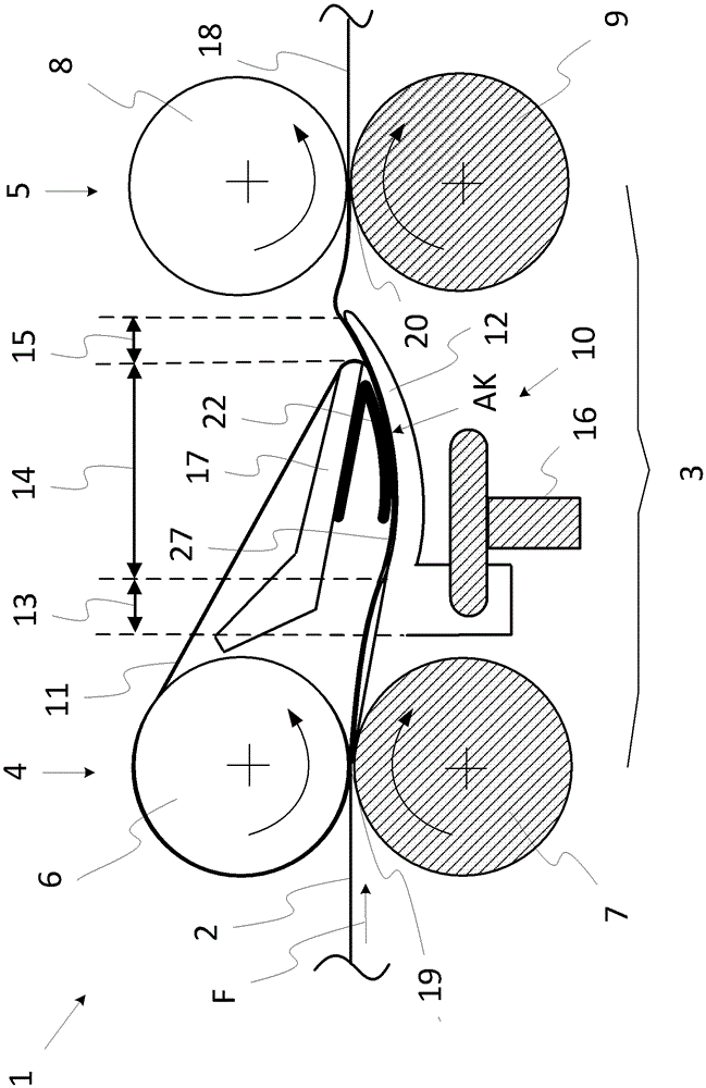
[0028] figure 1 A schematic side view of a drafting roller 1 of a spinning machine with a conventional fiber guiding device 10 (as known in the prior art) is shown. The spinning machine may in particular be a spinning preparation machine such as a flyer spindle or a draw frame or a spinning machine such as a ring spinning machine. Drafting rollers 1 are arranged to draft feed fiber bundles 2 , for example fiber slivers or rovings, in a drafting zone 3 so that a uniformly raised fiber bundle 18 is obtained. The drafting zone 3 is located between the nip line 19 of the pair of rollers 4 on the infeed end and the nip line 20 of the pair of rollers 5 on the delivery end.

[0029] Similar to the bottom roller 9 on the delivery end, the bottom roller 7 on the infeed end is mounted in a stationary support and driven. The bottom roller 7 on the infeed end is assigned to the movable and loaded top roller 6 on the infeed end so that the extracted fiber bundle 2 is clamped on the top r...


PUM


Abstract

The invention relates to a drafting unit (1) for processing at least one fiber sliver (2) in a spinning machine, wherein the drafting unit (1) has at least one drafting zone (3) which is formed between a feed roller pair (4) and a delivery roller pair (5), wherein the feed roller pair (4) and the delivery roller pair (5) are each made up of a lower roller (7, 9) and an upper roller (6, 8), and the drafting zone (3) is assigned a fiber guiding device (10) which has a fiber guiding tape (11), circulating about a roller of the feed roller pair (4), and a fiber guiding element (12) which bears against the fiber guiding tape (11), wherein the at least one fiber sliver (2) is guided between the fiber guiding tape (11) and the fiber guiding element (12). In order to ensure sufficient guidance of the fiber sliver (2) in the fiber guiding device (10), the fiber guiding element (12) is configured as an elastic spring element which has a fiber guiding face (27).

Description

technical field [0001] The invention relates to a drafting roller for processing at least one fiber bundle in a spinning machine, wherein the drafting roller has at least one drafting zone formed between a pair of feed rollers and a pair of delivery rollers, wherein the The pair of feed rollers and the pair of delivery rollers each consist of bottom and top rollers, and the drafting zone is assigned to a fiber guiding mechanism having a fiber guiding belt arranged around one of the pair of feeding rollers and There is a fiber guiding element which contacts the fiber guiding strip, so that the at least one fiber bundle is guided between the fiber guiding strip and the fiber guiding element. Background technique [0002] Most drafting rollers of this type have an upper infeed roller mounted in a rest position and driven, and a lower delivery roller mounted in a rest position and driven. The upper feed roller is assigned to the upper feed roller which is movable and loaded suc...

Claims


Application Information

Patent Timeline
Patent Type & Authority Applications(China)
IPC IPC(8): D01H15/00D01H1/02D01H5/26D01H5/70D01H5/50D01H5/20
CPCD01H5/26D01H5/20D01H5/50D01H5/70
Inventor L.马里纳G.施内德
Owner MASCHINENFABRIK RIETER AG
Why Eureka
Try Eureka