Electrically operated shaving appliance

A kind of equipment, electric technology, applied in the direction of metal processing, etc., can solve the problem of high manufacturing cost of shaving equipment

Inactive Publication Date: 2010-09-08
BRAUN GMBH
View PDF2 Cites 0 Cited by
  • Summary
  • Abstract
  • Description
  • Claims
  • Application Information

AI Technical Summary

Problems solved by technology

Likewise, the deflection device here consists of a greater number of components, which can lead to higher manufacturing costs than the shaving device

Method used


Image

  • Electrically operated shaving appliance
  • Electrically operated shaving appliance
  • Electrically operated shaving appliance

Examples


Embodiment Construction

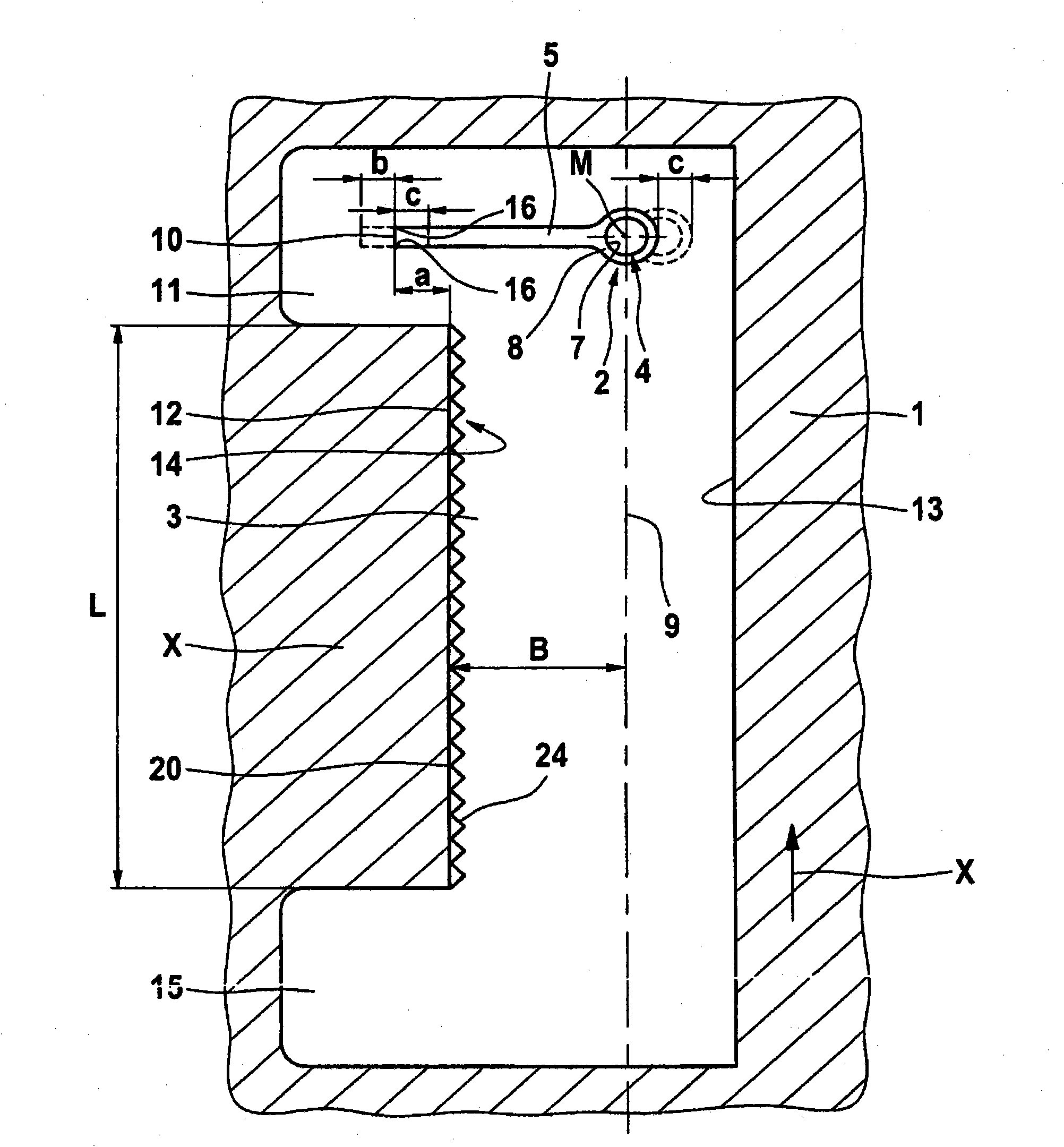
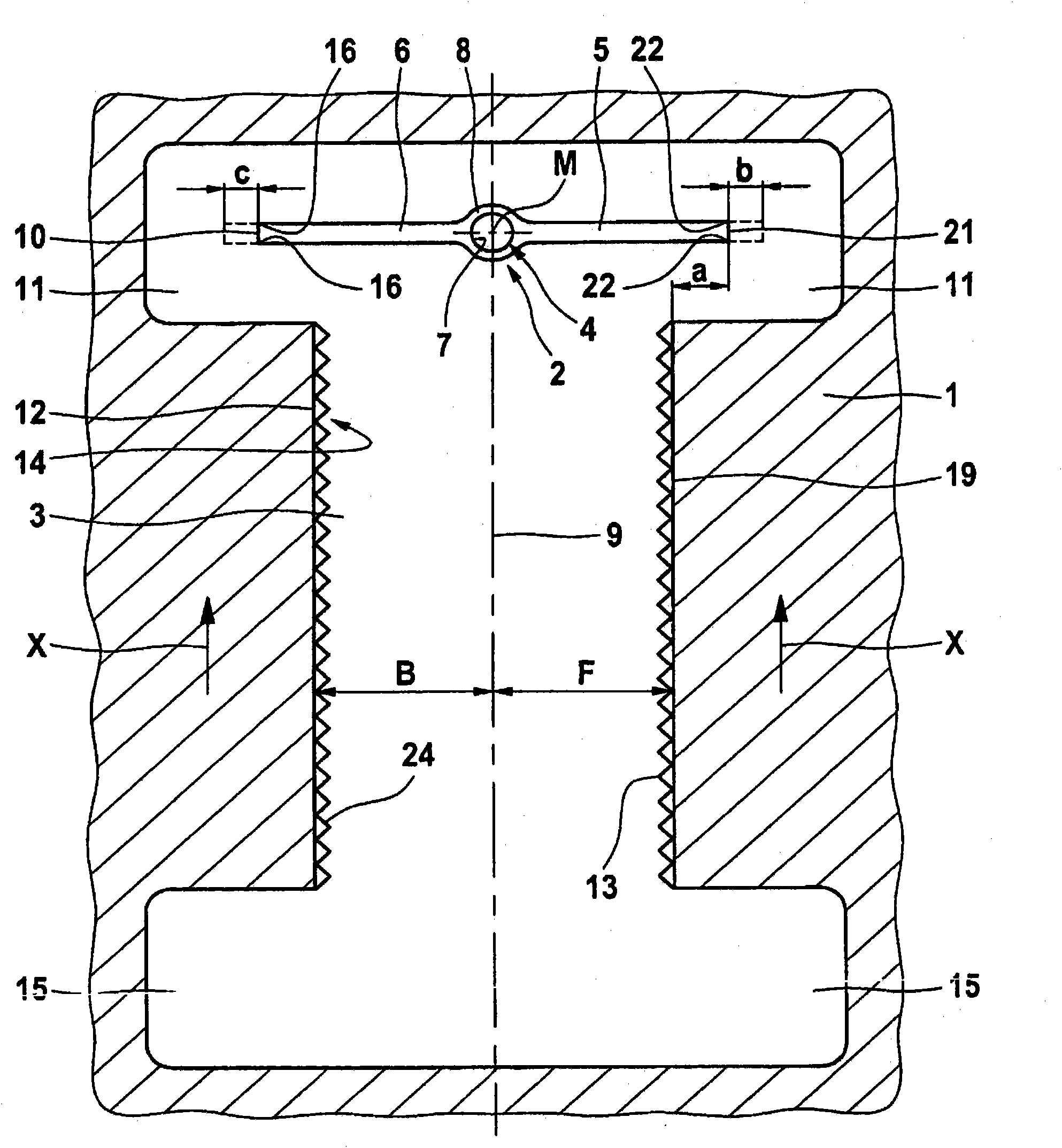
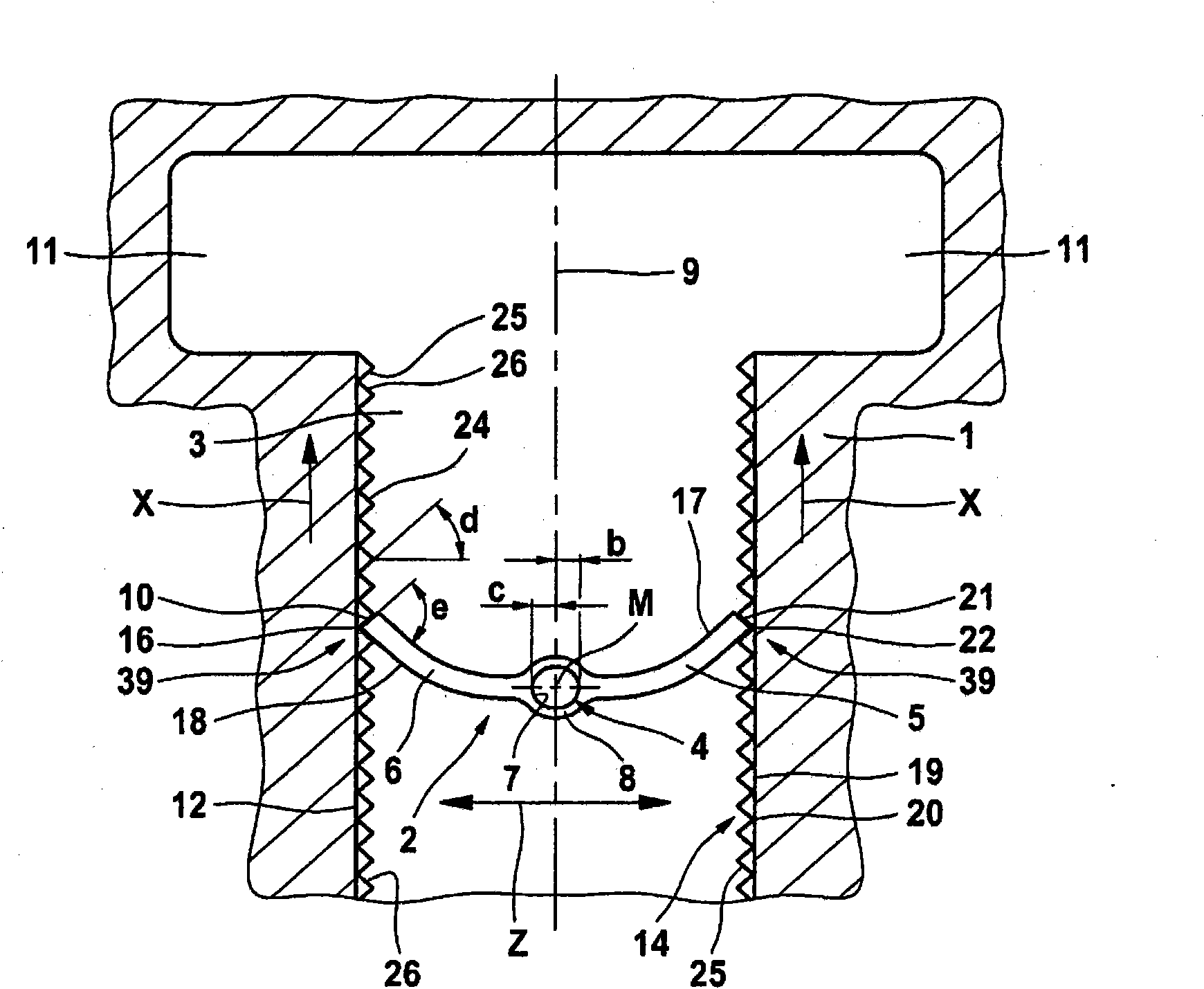
[0025] First, it should be mentioned that, Figure 1 to Figure 4 Only one section of the razor housing 1 is shown, on which the deflection device 2 can act. The illustrations are sufficient to clearly illustrate the invention. However, in order to better understand the connection between the present invention and the razor housing of the shaving apparatus, Figure 5A shaving device 25 is shown having a first cutting system 28 on the front face 26 of the shaving device 1 which can be brought into an extended or retracted position. The cutting system 28 consists of a long hair cutter having comb-shaped upper and lower blades 30, 31 which slide along each other and extend transversely to the razor housing 1 and protrude forward from said housing so as to way to better reach the user's skin surface. On the front side, a second cutting system 32 is arranged with two razor foils 33 , 34 next to each other and corresponding thereto two lower blades (not shown) swinging back and fo...


PUM


Abstract

The invention relates to an electrically operated shaving appliance (25) comprising a drive element (4) that can be driven by an electric motor in a back-and-forth movement and drives at least one cutting system (28, 32), the shaver housing (1) thereof being displaceable into a pulled-out or inserted position by means of a guiding arrangement (29) that can also be moved in relation to the shaver housing (1). Part of the movement of the drive element (4) is deviated by a deviation device (2) in the direction (X, Y) of displacement. According to the invention, the deviation device (2) consists of at least one wall (12, 19) extending in the direction (X; Y) of displacement thereof and at least one elastic element (5, 6) connected to the drive element (4) in a fixed manner, said elastic element (5, 6) coming into contact with the wall (12, 19) after the displacement of the shaver housing (1) out of its starting or end position, and is then bent between the drive element (4) and the wall (12, 19) in the direction (X or Y) of displacement. Means (14, 16) are provided at the contact point (39) between the elastic element (5, 6) and the wall (12, 19), said means partially deviating the displacement path (b or c) of the drive element (4), created during the advancing movement (Z), from the elastic element (5, 6) towards the shaver housing (1), thereby causing the housing to move in the direction (X or Y) of displacement. During the return movement, the elastic element (5 or 6) is only in sliding contact with the associated wall (12, 19). The invention enables an especially simple electromotively driven forwards and backwards movement of a cutting device.

Description

technical field [0001] The invention relates to an electric shaving device according to the preamble of claim 1 . Background technique [0002] A shaving device according to the preamble of claim 1 is known from DE 195 31 013 C1. according to image 3 , both the first and the second cutting system are designed to be located on the upper side of the shaving device herein. The first cutting system consists of two adjacently arranged perforated foils (generally identified as upper blades) and two lower blades arranged therebelow, said lower blades being in sliding contact with the upper blades. This first cutting system is identified as a so-called short hair cutting system K1, K2. The mid-length hair cutter L2 is designed to be positioned between two short hair cutters, and it is intended to be used to cut slightly longer hairs to an extent such that the remaining stubble is more suitable for cutting by the short hair cutter. [0003] in accordance with figure 1 On the fr...

Claims


Application Information

Patent Timeline
IPC IPC(8): B26B19/10B26B19/04B26B19/06B26B19/38
CPCB26B19/102B26B19/04B26B19/3886B26B19/06
Inventor A·埃尔特
Owner BRAUN GMBH
Why Eureka
Try Eureka