
Pressure regulator for a fuel supply unit

A pressure regulator and conveying unit technology, which is applied in fluid pressure control, control/regulation systems, instruments, etc., can solve the problems of complex manufacturing valve body production process of pressure regulators, complicated insertion of pressure regulators, etc., and achieves simple assembly, The effect of small construction spaces

Active Publication Date: 2010-04-14
VTESCO TECH GMBH
View PDF6 Cites 0 Cited by
  • Summary
  • Abstract
  • Description
  • Claims
  • Application Information

AI Technical Summary

Problems solved by technology

[0003] A disadvantage of this known pressure regulator is that it requires a particularly complex production process for the manufacture of the valve body
In addition, the ball designed as a valve body requires a particularly complex insertion into the pressure regulator

Method used


Image

  • Pressure regulator for a fuel supply unit
  • Pressure regulator for a fuel supply unit
  • Pressure regulator for a fuel supply unit

Examples


Embodiment Construction

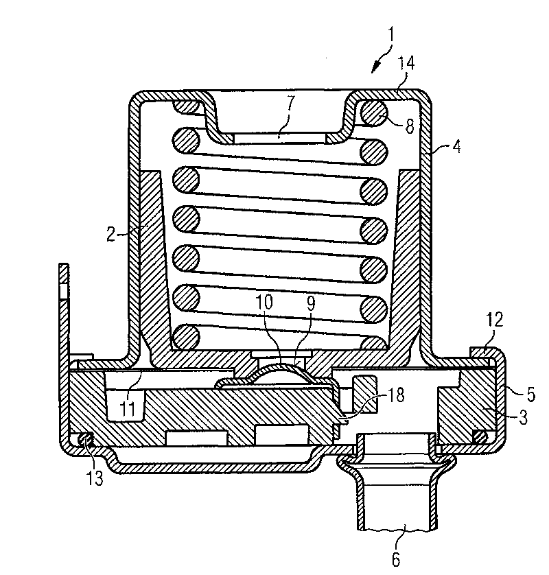
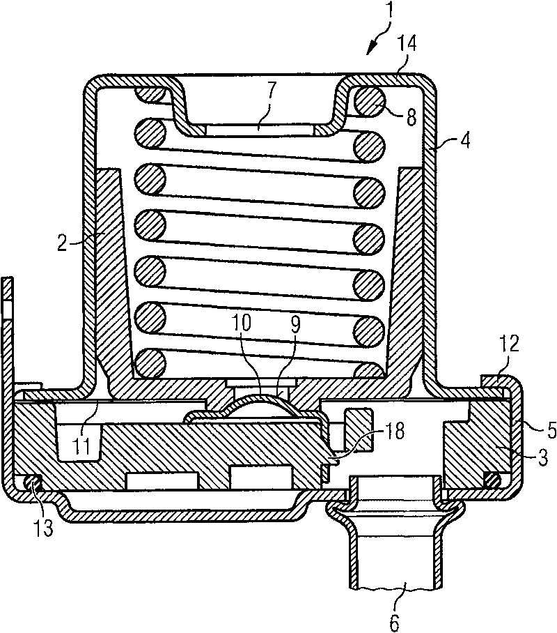
[0019] figure 1 A pressure regulator according to the invention designed as a straight-through valve is shown, which has a housing 1 and a piston 2 which is displaceably arranged in the housing 1 . The pressure regulating valve serves to limit the maximum pressure in the feed line (not shown) of the motor vehicle's fuel tank. The housing 1 has two housing parts 4 , 5 spaced apart from the carrier body 3 . The pressure regulator has a connection 6 and an outlet 7 for the pressure line. The piston 2 biases the valve seat 9 against the valve body 10 via a spring 8 designed as a helical spring.

[0020] A membrane 11 connected to the support body 3 and the piston 2 seals the upper area of ​​the piston 2 from the lower area of ​​the piston 2 . This ensures that, when pressure is present in the connection port 6 , the piston 2 is loaded against the force of the spring 8 and, above a predetermined pressure, the piston 2 is displaced so that the valve seat 9 is lifted from the valv...


PUM


Abstract

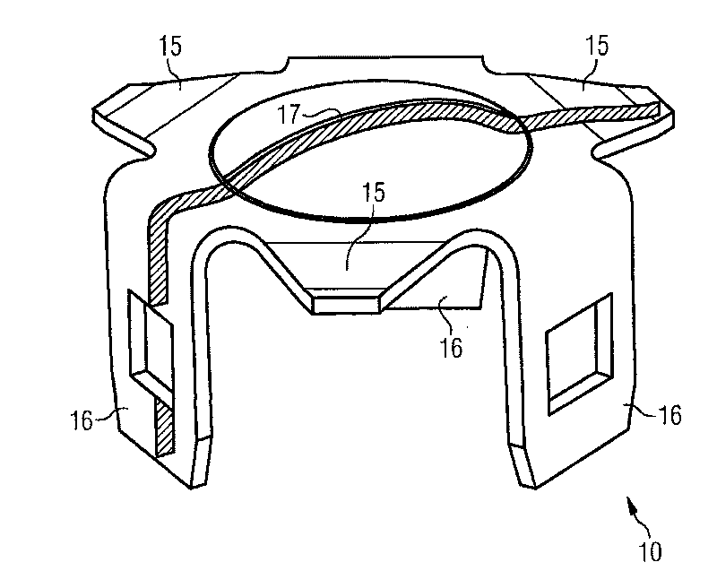
The invention relates to a pressure regulator for a fuel supply unit on a motor vehicle, with a valve body (10) embodied as a sheet metal piece, comprising an elastomeric coating (17) on the side thereof facing a valve seat (9). The pressure regulator is thus particularly simple to produce. The pressure regulator also has a reliable sealing at low pressures.

Description

technical field [0001] The invention relates to a pressure regulator for a fuel delivery unit of a motor vehicle, the pressure regulator has: a valve for connecting the connection port with the outlet when the pressure in the connection port exceeds a preset pressure; a valve body and the valve seat; and a spring member for biasing the valve body against the valve seat. Background technique [0002] Pressure regulators of this type are frequently used in today's motor vehicles for regulating the pressure in the feed line to the motor vehicle's internal combustion engine and are well known from practice. The valve body is mostly designed as a ball and seals against the seat below a preset pressure. The outlet is provided on a side of the valve seat opposite to the connection port. Above a preset pressure, the ball is lifted from the valve seat by the pressure in the connection port, allowing fuel to flow to the outlet port. For the necessary tightness, the ball must have p...

Claims


Application Information

Patent Timeline
Patent Type & Authority Patents(China)
IPC IPC(8): F02M69/54F02M61/16G05D16/02F02M63/00
CPCG05D16/068F02M2200/9015F02M2200/8069F02M2200/9038F02M69/54F02M37/0029F02M61/16F02M63/00G05D16/02
Inventor 德特勒夫·迪辛卡尔·埃克勒内·施密德
Owner VTESCO TECH GMBH
Learn More