
Multi-stage cooling middle liquid-separation air condensator

An air condenser and condenser technology, which is applied to steam/steam condensers, lighting and heating equipment, etc., can solve the problems of high production and operation costs, decreased fin utilization rate, and poor condensation effect, and achieves a reduction in production and operation costs. and operating costs, avoidance of steam leakage or steam short circuit, the effect of reducing thickness

Inactive Publication Date: 2007-08-29
TSINGHUA UNIV
View PDF0 Cites 34 Cited by
  • Summary
  • Abstract
  • Description
  • Claims
  • Application Information

AI Technical Summary

Problems solved by technology

During the condensation process, the liquid film gradually thickens, and in the long-term later, it will be a complex two-phase flow in which the liquid gradually increases, the thermal resistance will gradually increase, and the condensation effect will deteriorate seriously; at the same time, with the condensation of the steam, the amount of steam will gradually decrease. The steam flow rate in the tube drops significantly, the condensation effect degrades sharply, and the heat transfer coefficient decreases; the condensation process in a single tube process also leads to complex gas-liquid two-phase flow, which has great impact on system operation stability, flow resistance and system regulation. negative effect
On the air side, due to the increase in the thermal resistance of condensation heat transfer in the tube, the temperature of the outer tube wall decreases, resulting in a decrease in the utilization rate of the fins
In order to solve the above-mentioned problems, traditional air-cooled condensers increase the heat transfer area to meet the demand for heat transfer. The volume and weight are large, and the production and operation costs are high.

Method used


Image

  • Multi-stage cooling middle liquid-separation air condensator
  • Multi-stage cooling middle liquid-separation air condensator
  • Multi-stage cooling middle liquid-separation air condensator

Examples


Embodiment Construction

[0022] Further illustrate the present invention below in conjunction with accompanying drawing.

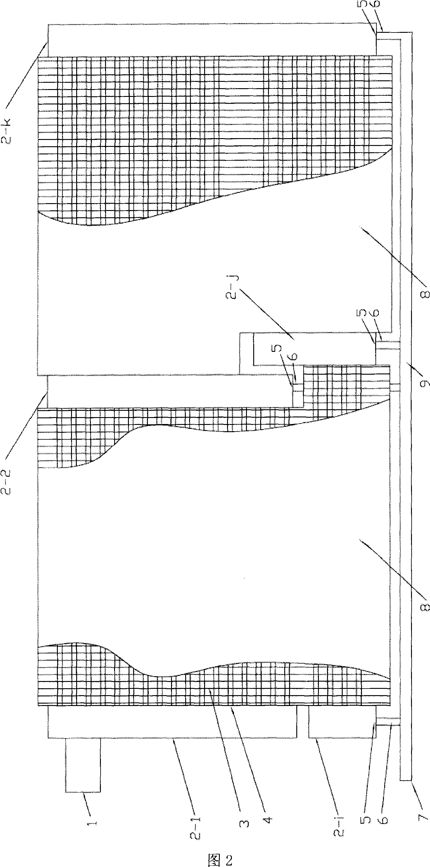
[0023] Fig. 2 is the front view of the present invention (serial horizontal pipe type), wherein, 1 air inlet, 2-j the j header, 2-k single turning header, 2-i the last header, 3 fins , 4 heat exchange tubes, 5 liquid outlet air seal device, 6 liquid discharge pipe, 7 condensate outlet, 8 shell, 9 condensate collecting pipe. A multi-stage cooling intermediate liquid-splitting air condenser, suitable for cooling of large-scale power engineering, composed of multiple stages A, B..., the number of stages can be adjusted according to needs, this picture shows the intermediate separation with two-stage cooling Liquid air condenser. There are headers between the stages to transfer steam. Except for the first stage which includes steam inlet 1 and condensate outlet 7, the rest of the stages only contain headers 2-j, fins 3, heat exchange tubes 4, and liquid outlets. Sealing device 5, dr...


PUM


Abstract

Multiple-refrigeration Middle-delivery aerial condenser belongs to thermodynamic equipment technology domain. It composes of multi stages, and every stage is connected by the channels; every stage has two flow stages in which the steam floats to opposite direction; the air input is connected with the first channel , and the first channel is connected with the second channel by a row of parallel distribution heat exchange tube of the first stage; the second channel is connected with the heat exchange tube of next stage; apostrophe ,until get to the last channel; there are fins set out of the heat exchange tube; the shell is set out of the heat exchange tube and fins. The steam is put into the heat exchange tube of the first stage to refrigerate through the steam input and the first channel, and the air-liquid mixture flows into channel, and then the liquid and the air are separated; the steam gets into the heat exchange tube of next stage. This invention is suitable for large power engineering refrigeration, and it has efficient condensation capacity and large coefficient of heat transmission; the heat transfer area of the equipment is made use of sufficiently and efficiently; the fabric is flexible and smart, the applicability of the space is high.

Description

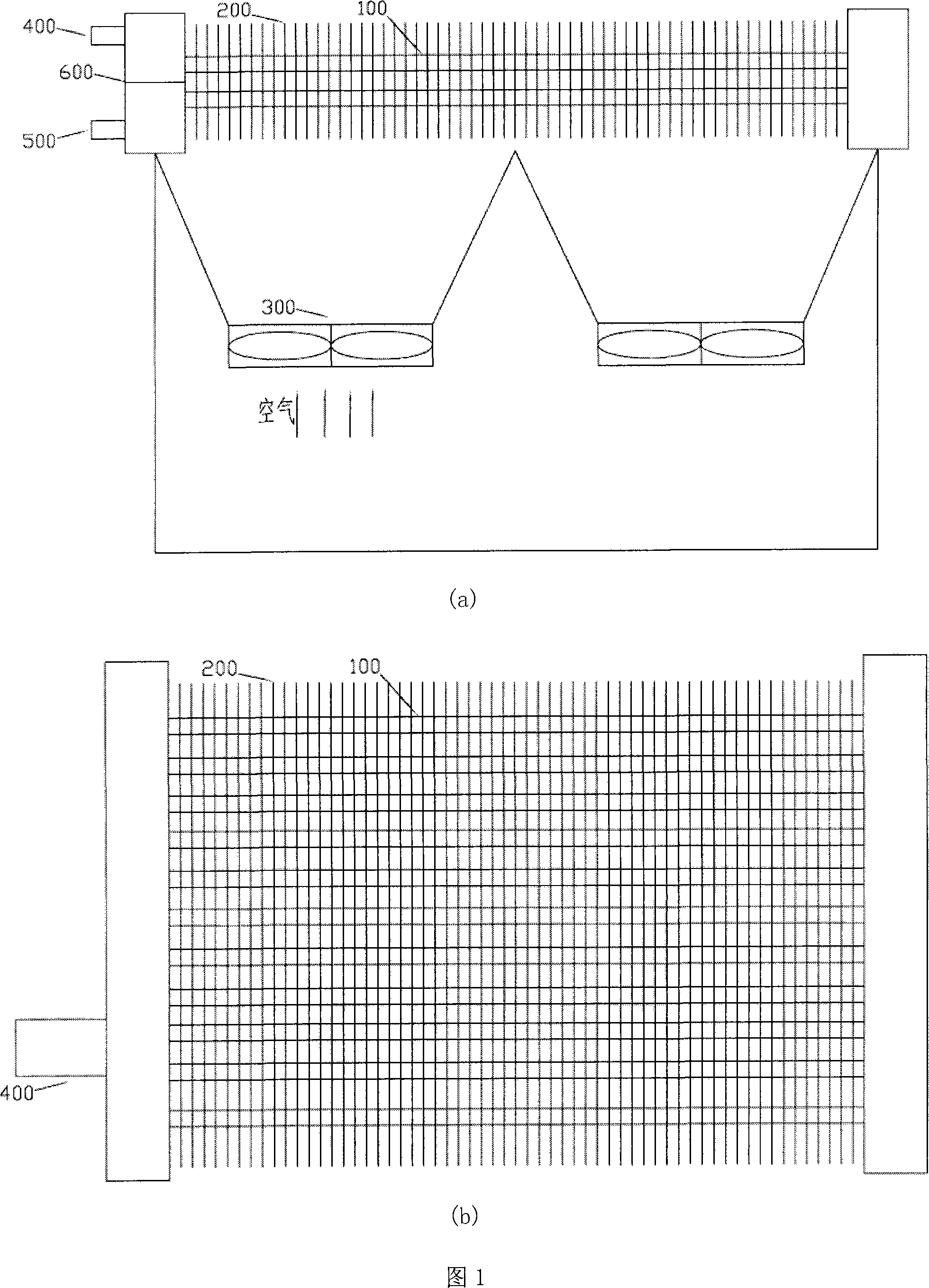
technical field [0001] The invention relates to a multi-stage cooling intermediate liquid separation type air cooling condensation heat exchanger, which belongs to the technical field of thermal equipment. Background technique [0002] Air condenser is a kind of thermal equipment, which is widely used in energy system, power engineering, chemical and petrochemical industries, such as air condenser in thermal power station, air-cooled condenser in air-conditioning engineering and refrigeration system, etc. Figure 1 shows a traditional air condenser used in a power station. The main components are finned tube bundles and fans. As shown in Figure 1, Figure (a) is a front view of a traditional air condenser; Figure (b) is a top view. Among them, 100-tube bundle, 200-fin, 300-fan, 400-steam inlet, 500-condensate outlet, 600-baffle. Traditional air condensers rely on the convective heat transfer of air outside the tubes, and the coolant vapor condenses inside the tubes. The inl...

Claims


Application Information

Patent Timeline
IPC IPC(8): F28B1/06
Inventor 彭晓峰吴迪王珍陆规
Owner TSINGHUA UNIV
Learn More