Magnetically controlled sputtering process for synthesizing superhard film
A magnetron sputtering and new process technology, applied in sputtering plating, metal material coating process, ion implantation plating, etc., to enhance the bonding force, prevent movement and growth, and prevent mutual diffusion.
- Summary
- Abstract
- Description
- Claims
- Application Information
AI Technical Summary
Problems solved by technology
Method used
Image
Examples
Embodiment 1
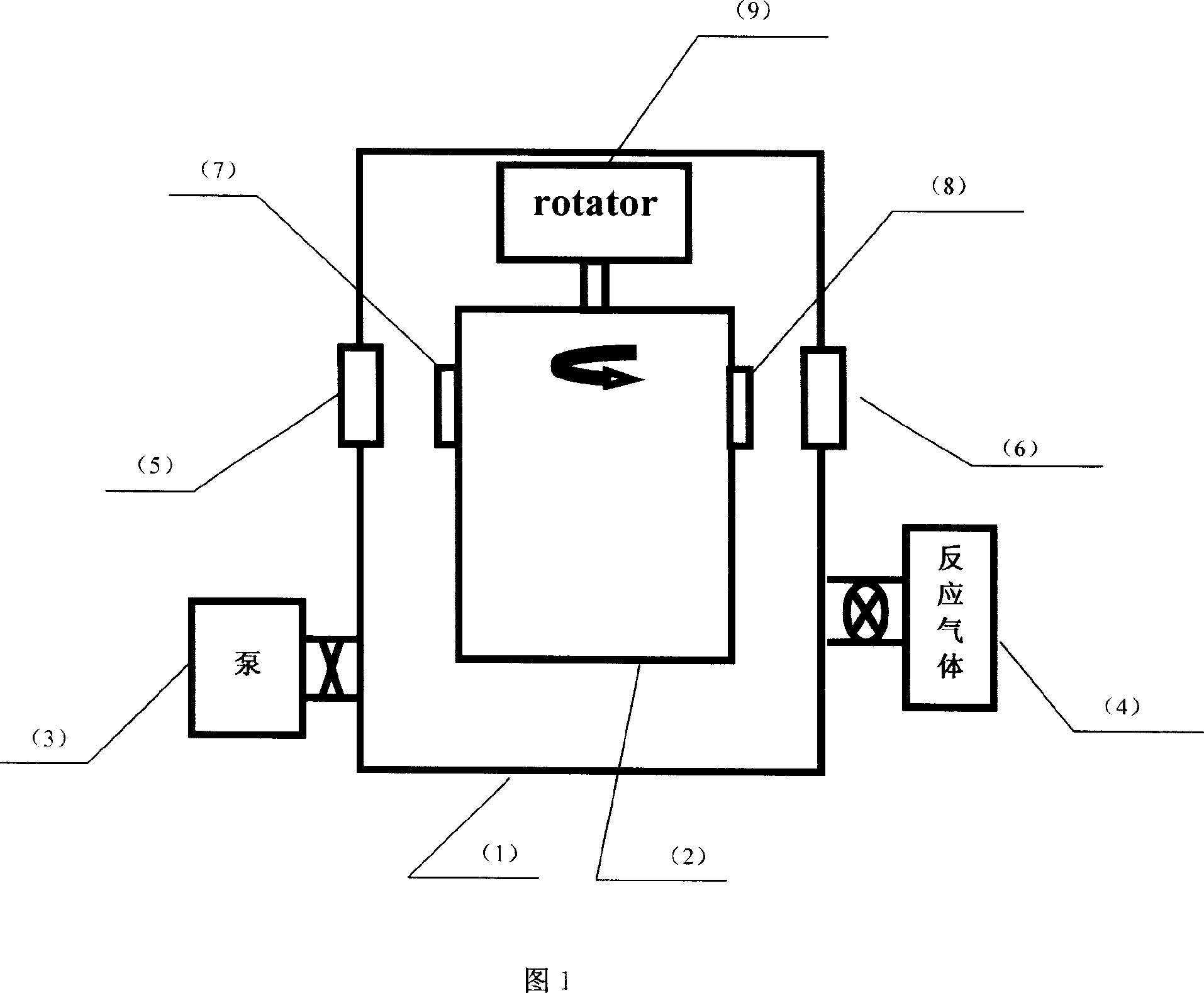
[0027] Coating machine used in Example 1 (synthesis of elemental CrN thin film under new process): a domestically produced SA-6T coating machine from the School of Physics and Electronic Information of Tianjin Normal University. The specific operation steps are: a. Install the metal Cr target material to be plated on the magnetron sputtering target (5) or (6); b. ultrasonically clean and dry the base material such as the sample substrate stainless steel or silicon wafer, and (7,8) samples are installed on the turntable of the sample rack (2); c. the vacuum chamber (1) is pumped to 4.0×10 with the pumping system (3) -3 Pa and heat the vacuum chamber temperature to 250°C; d. Clean the sample substrate with Ar ion sputtering at -600V bias for 10 minutes; e. Turn on the DC power supply connected to the Cr target, and gradually increase the voltage until it glows, Then, adjust the power to 1.0kW, and pre-sputter for 10 minutes (the sample is away from the target), f. During the ent...
Embodiment 2
[0028] Embodiment 2 (synthesis of ZrN nano-element thin film under the new process) the metal Zr target material to be plated is installed on the magnetron sputtering target (5) or (6). The substrate is sputtered with Ar ions under -600V bias Clean the sample substrate by sputtering for 8 minutes, turn on the DC power supply connected to the Zr target, gradually increase the voltage until it glows, then adjust the power to 1.5kW, and pre-sputter for 15 minutes (the sample is away from the target). The performance indicators are shown in Table 1 The fourth line, that is, the nanohardness reaches 22.75GPa, and the compressive stress also decreases by 4.8GPa. All the other are with embodiment 1.
Embodiment 3
[0029] Embodiment 3 (synthesis of CrN / ZrN nano-multilayer film under the new process) concrete steps are: the metal Cr to be plated, the Zr target material is installed on the respective magnetron sputtering targets (5), (6), and the base material Clean the sample substrate with Ar ion sputtering at -600V bias for 10 minutes; pre-sputter Cr and Zr targets for 20 minutes, turn on the DC power supply of Cr and Zr targets at the same time, gradually increase the voltage until it glows, and adjust the power to 1kW, 1.5kW, pre-sputtering for 20 minutes (the sample is away from the target), the Cr and Zr metal targets maintain the power; then, without substrate bias, first deposit 55nm of pure metal Cr on the sample substrate; and gradually control the introduction of 0.8ml N of / s traffic 2 Gas and NH at a flow rate of 0.1ml / s 3 At the same time, the substrate bias voltage was gradually increased to -200V. At this time, the stepper motor (9) was turned on to allow the sample to ro...
PUM
| Property | Measurement | Unit |
|---|---|---|
| Nanohardness | aaaaa | aaaaa |
| Nanohardness | aaaaa | aaaaa |
| Compressive stress | aaaaa | aaaaa |
Abstract
Description
Claims
Application Information
 - R&D
- Intellectual Property
- Life Sciences
- Materials
- Tech Scout
- Unparalleled Data Quality
- Higher Quality Content
- 60% Fewer Hallucinations
Browse by: Latest US Patents, China's latest patents, Technical Efficacy Thesaurus, Application Domain, Technology Topic, Popular Technical Reports.
© 2025 PatSnap. All rights reserved.Legal|Privacy policy|Modern Slavery Act Transparency Statement|Sitemap|About US| Contact US: help@patsnap.com

