Gas directional radiating device
A technology of directional radiation and radiators, which is applied in the field of directional radiators, can solve the problems of unusable places with high-power power supplies, poor power safety, and low power, and achieve the effects of safe and reliable use, short heating time, and low cost
- Summary
- Abstract
- Description
- Claims
- Application Information
AI Technical Summary
Problems solved by technology
Method used
Image
Examples
specific Embodiment approach 1
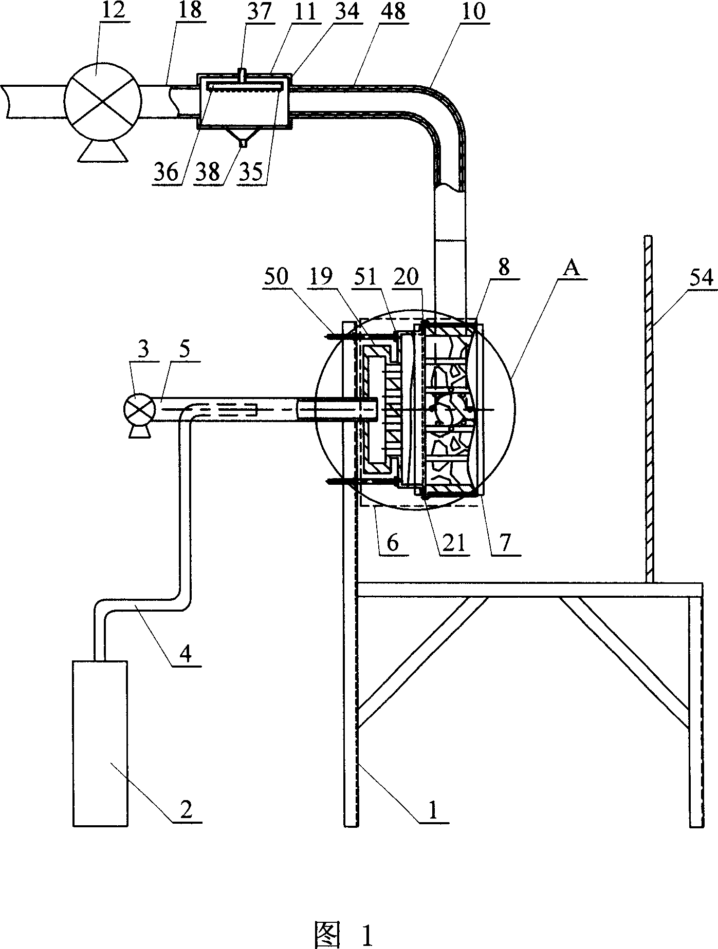
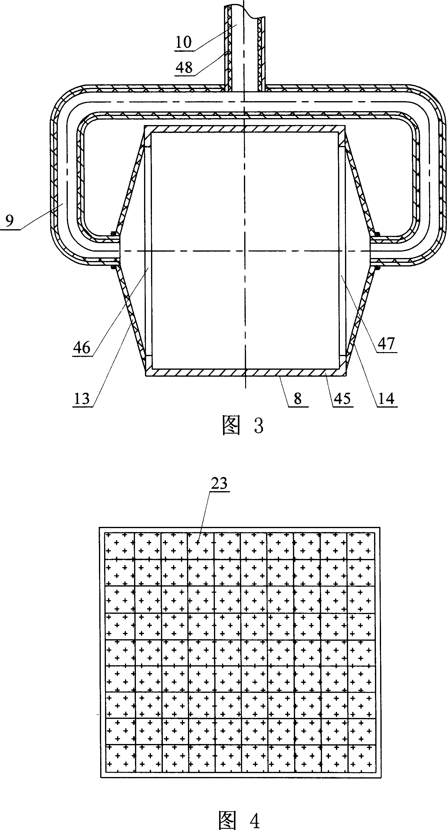
[0006] Specific embodiment 1: This embodiment will be explained with reference to Figure 1, Figure 3 and Figure 11. This embodiment consists of bracket 1, gas cylinder 2, blower 3, gas pipe 4, conveying pipe 5, burner assembly 6, and directional radiation device 7. The flue gas delivery frame 8, the first flue gas elbow 9, the second flue gas elbow 10, the water spray heat exchanger 11, the induced draft fan 12, the flue gas pipe 18, the bolt 50 and the nut 51; The lower end of the gas pipe 4 is connected with the gas outlet of the gas cylinder 2, the upper end of the gas pipe 4 is installed in the conveying pipe 5 and is in clearance fit with the conveying pipe 5, and the rear end of the conveying pipe 5 is connected with the air outlet of the blower 3. The conveying pipe The front end of 5 is installed in the burner assembly 6, and the outer end of the burner assembly 6 is fixedly equipped with a nut 51. The two ends of the bolt 50 are respectively connected to the nut 51 and th...
specific Embodiment approach 2
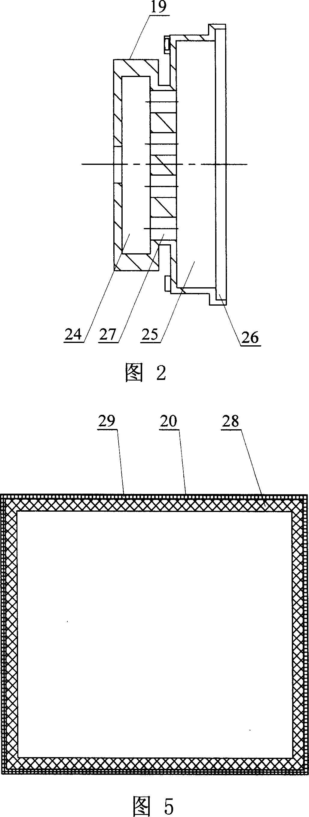
[0007] Specific embodiment two: this embodiment is described with reference to Fig. 1, Fig. 2, Fig. 4 and Fig. 11. The burner assembly 6 of this embodiment is composed of a burner 19, a heat insulation frame 20, and a connecting frame 21; 19 is composed of a shell and a solar fire infrared combustion surface layer 23; the shell is composed of a rear air inlet chamber 24, a connecting channel 27, a middle air inlet chamber 25 and a front shoulder hole 26 in turn; the rear air inlet chamber 24 and the middle inlet The air chambers 25 are communicated through a set of connecting passages 27. The middle air inlet chamber 25 is communicated with the front shoulder hole 26. The front shoulder hole 26 is fixedly equipped with a solar fire infrared combustion surface 23. The front end of the delivery pipe 5 Installed in the rear air inlet cavity 24, the heat insulation frame 20 is sleeved on the shell and located at the position of the solar fire infrared combustion surface layer 23, and ...
specific Embodiment approach 3
[0008] Specific implementation mode 3: This embodiment will be described with reference to Figures 4 and 5. The thermal insulation frame 20 of this embodiment is composed of an aluminum silicate felt thermal insulation layer 28 and a wire mesh frame 29; the inner wall of the wire mesh frame 29 is equipped with silicic acid Aluminum felt insulation layer 28. Such arrangement can play the role of heat insulation and heat preservation for the solar fire infrared combustion surface layer 23. Other components and connection relationships are the same as in the second embodiment.
PUM
 Abstract
Description
Claims
Application Information
 - R&D Engineer
- R&D Manager
- IP Professional
- Industry Leading Data Capabilities
- Powerful AI technology
- Patent DNA Extraction
Browse by: Latest US Patents, China's latest patents, Technical Efficacy Thesaurus, Application Domain, Technology Topic, Popular Technical Reports.
© 2024 PatSnap. All rights reserved.Legal|Privacy policy|Modern Slavery Act Transparency Statement|Sitemap|About US| Contact US: help@patsnap.com


