
Heat pump hot-water air-conditioning unit

A heat pump hot water and air conditioner technology, applied in heat pumps, fluid heaters, lighting and heating equipment, etc., can solve the problems of reduced condenser efficiency, insufficient replenishment, and small water storage tanks, so as to improve heating efficiency, reduce energy consumption, etc. Load, easy installation effect

Inactive Publication Date: 2007-08-15
罗国志
View PDF0 Cites 5 Cited by
  • Summary
  • Abstract
  • Description
  • Claims
  • Application Information

AI Technical Summary

Problems solved by technology

Second, in the process of using hot water, cold water enters the water storage tank at the same time, so that the cold and hot water are quickly mixed, the temperature of the high-temperature hot water is transferred to the low-temperature cold water, and the heat source of the heat pump water heater is insufficient, resulting in a rapid drop in the temperature of the hot water , which seriously affects continuous use
Third, during the operation of the heat pump, the water temperature rises due to the built-in condenser during the heat release process. As the water temperature rises, the condensation efficiency of the condenser will be affected, resulting in a decrease in the heating effect of the heat pump.
Fourth, due to the reduced efficiency of the condenser of the heat pump water heater, the load on the compressor and other equipment is increased, thereby affecting the operation and life of the heat pump water heater
Fifth, due to the high requirements for the production process and materials of the pressure-bearing water storage tank, the current storage tank of the heat pump water heater is relatively small, which causes the daily heating capacity of the main unit of the heat pump water heater to far exceed that of the water storage tank full of water heat storage capacity
As a result, the heat pump cannot perform cooling at will, and cannot effectively use heat storage during cooling according to usage habits, so that the use function of the heat pump water heater is single
Sixth, the heat pump water heater cannot centrally and continuously supply constant temperature hot water, and the high requirements are poor in usability
This is due to the poor heating efficiency of current heat pump water heaters, the inability to make full use of heat pump water heaters for cooling, the water temperature drops during continuous use, and poor comfort, which hinder the application and promotion of heat pump water heaters.

Method used

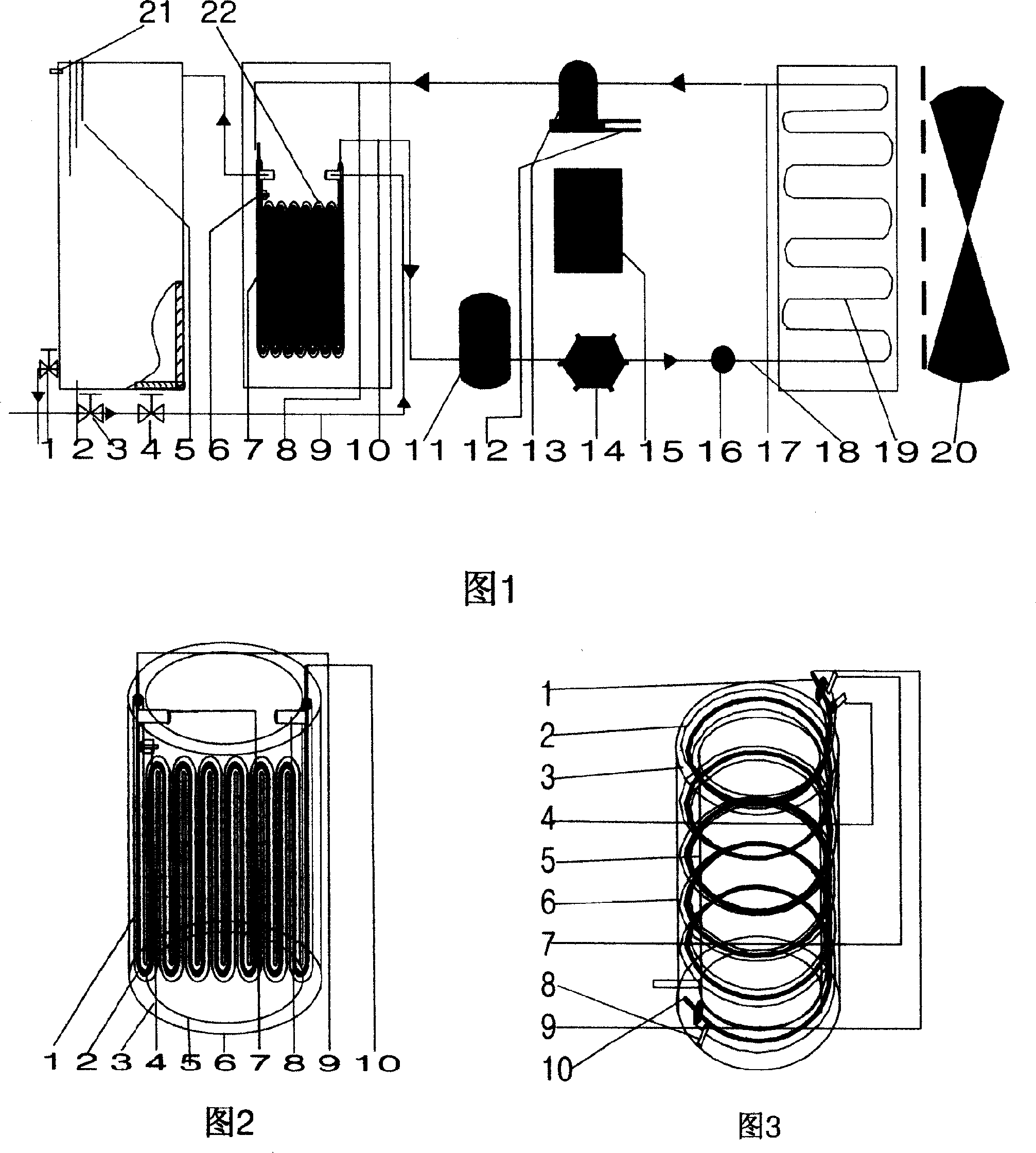

Image

  • Heat pump hot-water air-conditioning unit

Examples


Embodiment Construction

[0015] The specific structure and embodiments of the present invention will be further described below in conjunction with the accompanying drawings.

[0016] Fig. 1 is a schematic structural diagram of an embodiment of a heat pump hot water air conditioner provided by the present invention. The heat pump hot water air conditioner mainly includes a compressor (1-13), an evaporator (1-19) connected to the suction inlet and outlet of the compressor through low-pressure liquid pipelines (1-17, 18), and a pipe-in-pipe A condenser (1-7), and a throttling device (1-11) and a dry filter (1-14) arranged on the low-pressure liquid pipeline (1-17, 18) between the tube-in-tube condenser and the evaporator , the expansion valve (1-16) is connected. The pipe-in-pipe condenser (1-7) is arranged between the inner tank and the outer tank of the normal pressure thermal insulation water storage tank (1-2), or is independently installed outside the normal pressure thermal insulation water stora...


PUM


Abstract

The invention relates to a hot pump hot water air conditioner which designs condenser into tube-in-tube condenser. The invention arranges tube-in-tube condenser in bended type or screw tube type between inner and outer containers of a thermal-insulated water tank, or mounted outside a normal-pressure thermal-insulated water tank, wherein two ends of the condenser are respectively arranged with electromagnetic valves. The invention uses water valve and temperature controller to refrigerate and supply hot water. The invention has the advantages in high efficiency, and avoids temperature reduction, to supply constant-temperature hot water, works stably and reduces noise.

Description

technical field [0001] The invention relates to a heat pump hot water air conditioner device for heating and cooling in the field of thermodynamics and thermodynamics. technical background [0002] The existing heat pump water heater is mainly composed of a compressor, a condenser placed in a water storage tank, a throttling device, an evaporator, a fan, a pressurized or slightly pressurized water storage tank, and a controller. In the water tank, this requires the water storage tank of the heat pump water heater to be filled with cold water to perform heat exchange more fully, which causes the following disadvantages: First, the heat pump should be used for a long time to heat the whole tank of cold water. Second, in the process of using hot water, cold water enters the water storage tank at the same time, so that the cold and hot water are mixed quickly, the temperature of the high-temperature hot water is transferred to the low-temperature cold water, and the heat source ...

Claims


Application Information

Patent Timeline
Patent Type & Authority Applications(China)
IPC IPC(8): F25B30/02F24H4/04
Inventor 罗国志
Owner 罗国志
Learn More