
Decompression drying processing device

A drying treatment and mounting technology, applied in the direction of pretreatment of surface, drying of solid materials, drying of solid materials without heating, etc., can solve the problems of heavier top plate weight, foreign matter on the coating film surface, and mechanical hand interference, etc., to prevent interference. , The effect of preventing foreign matter on the surface and prolonging the exhaust time

Active Publication Date: 2007-08-08
艾美柯技术株式会社
View PDF1 Cites 8 Cited by
  • Summary
  • Abstract
  • Description
  • Claims
  • Application Information

AI Technical Summary

Problems solved by technology

[0006] On the other hand, as the size of the glass substrate for liquid crystal displays increases, the thickness of the robot arm that carries the substrate into and out of the chamber of the reduced-pressure treatment device also increases. Entering the chamber, there may be interference between the robot arm or the glass substrate and the top plate
[0007] Also, if the size of the base plate becomes larger, the size of the top plate also becomes larger
As a result, considering that the weight of the top plate also becomes heavy, and a part hangs down to contact the coating liquid, it is difficult to narrow the gap between the top plate and the coating liquid (substrate surface) more than necessary.
[0008] As a result, since the cross-sectional area of ​​the exhaust port between the top plate and the substrate surface cannot be reduced more than necessary, the exhaust capacity cannot be suppressed, and surface foreign matter may be generated on the coating film on the substrate due to exhausting under a large amount of exhaust.

Method used


Image

  • Decompression drying processing device
  • Decompression drying processing device
  • Decompression drying processing device

Examples


Embodiment Construction

[0021] Embodiments of the present invention will be described below with reference to the accompanying drawings.

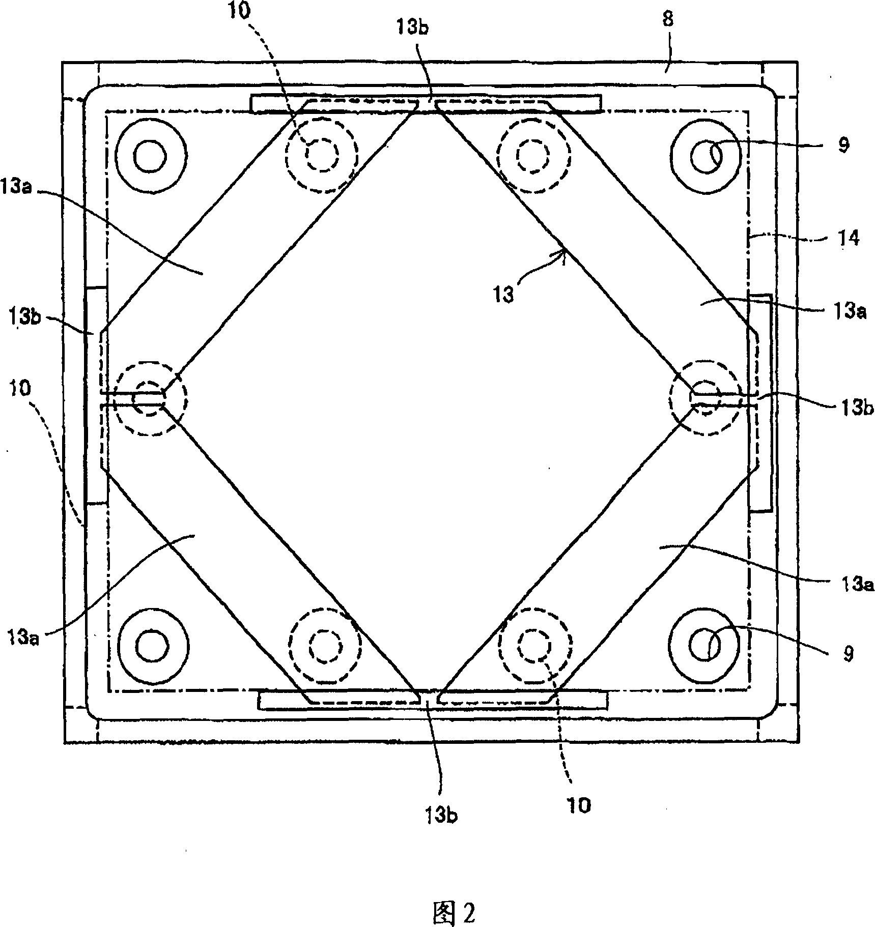
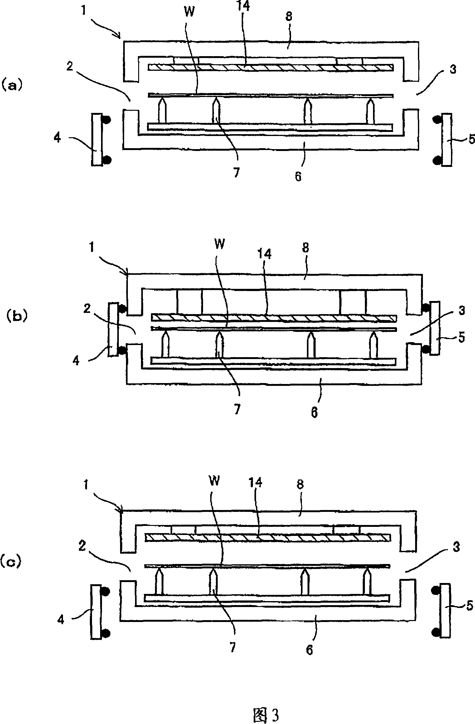
[0022] Fig. 1 is a cross-sectional view of a vacuum drying treatment device according to the present invention, and Fig. 2 is a view taken along the direction A-A of Fig. 1 .

[0023] In the reduced-pressure drying processing apparatus, an opening 2 for carrying in a substrate is formed on one side wall of a flat box-shaped chamber 1, and an opening 2 for carrying out a substrate is formed on the other side wall. Opening 3, and openings 2, 3 are opened and closed by doors 4, 5. These doors 4 and 5 are configured to be able to be opened and closed by a driving device not shown in the figure.

[0024] A support rod 7 (mounting member) for supporting the substrate W is provided on the bottom 6 of the chamber 1, and a plurality of (12 in the illustrated example) openings 9 for vacuuming are formed on the top 8 of the chamber 1. Cylinder units 10 as a lifting device ...


PUM


Abstract

The present invention is to provide a decompress drying process device capable of processing large size substrate with high efficiency. Said subject is resolved with following method: a top plate (14) is installed across a reinforcing plate (13) on the bottom of a bar (11) of a cylinder unit (10). The size of the top plate (14) can be made to a size for covering the substrate (W) adequately. Its thickness is thinner than that of the reinforcing plate (13) such that light weight is achieved. In addition, the reinforcing plate (13) comprises four combination plate (13a) having an angle of 45 degree with said top plate (14) when overlook, and connection section (13b) for connecting these combination plates (13a). Thus each combination plate (13a) is connected to form rectangle shaped reinforcing plate (13), and the reinforcing plate (13) is arranged staggering with the top plate (14) by 45 degree, thus distortion of the top plate (14) because of torsion can be prevented.

Description

technical field [0001] The invention relates to a device for drying a coating liquid (such as a protective liquid) coated on the surface of a substrate (such as a glass substrate for a liquid crystal display) under reduced pressure to form a coating film. Background technique [0002] Patent Document 1 discloses an apparatus that volatilizes a solvent from a coating liquid on a substrate surface, that is, dries the coating liquid to some extent to form a coating film. [0003] This patent document 1 is based on the following points: the thickness of the protective film formed by volatilizing the solvent from the protective solution applied to the surface of the semiconductor wafer under reduced pressure is affected by the size of the space above the semiconductor wafer. The rectifying plate above the semiconductor wafer is set to be able to move up and down, and the rectifying plate is moved up and down according to the pressure in the vacuum chamber, thereby controlling the...

Claims


Application Information

Patent Timeline
IPC IPC(8): H01L21/00H01L21/027G03F7/16G02F1/1333B05D3/04F26B5/04
Inventor 高濑真治楫间淳生
Owner 艾美柯技术株式会社
Learn More