Piercing device

A cylindrical body and negative pressure technology, applied in medical science, sensors, diagnostic recording/measurement, etc., can solve the problems of increased distance and difficulty in taking blood

Inactive Publication Date: 2007-07-25
ARKRAY INC
View PDF1 Cites 2 Cited by
  • Summary
  • Abstract
  • Description
  • Claims
  • Application Information

AI Technical Summary

Problems solved by technology

Therefore, in this case, the distance between the bleeding portion of the skin and the analysis member further increases, making it more difficult to properly collect blood with the above analysis member.

Method used


Image

  • Piercing device
  • Piercing device
  • Piercing device

Examples


Embodiment Construction

[0040] Hereinafter, preferred embodiments of the present invention will be described in detail with reference to the drawings.

[0041] Figures 1-7 are an embodiment of the present invention. As shown in FIG. 1, the puncture device A in this embodiment has a housing 2, a housing 39 surrounding a part of the housing 2, a display unit 21 for displaying an image, and operation switches 22 and 23. The display unit 21 is composed of, for example, a liquid crystal display or an LED display. The following control unit 9 is also provided in the housing 39.

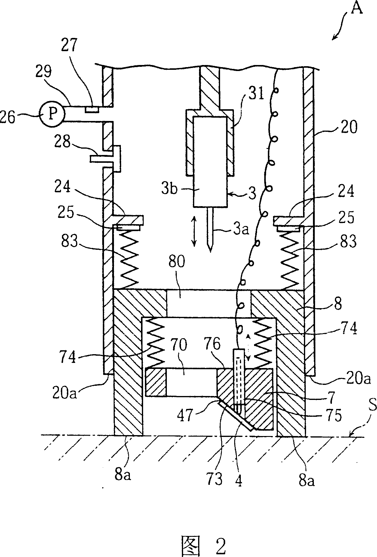
[0042] A cylindrical body 20 is formed at the front end of the lower end of the housing 2, and a cylindrical body 8 that is not integral with the housing 2 is embedded in the cylindrical body 20. The method of using the puncture device A of the present embodiment is to press the front end 8a of the cylindrical body 8 against the skin to be punctured.

[0043] As shown in FIG. 2, the cylindrical body 8 is supported by a spring 83 on th...


PUM


Abstract

A piercing device (A), comprising a piercing body (3) allowed to move forward in a first direction from the inner bottom part of a housing (2) to the tip end of a tubular body (8) and an analysis part (4) disposed in the tubular body (8), wherein the analysis part (4) is formed movable in a second direction when receiving a force in a second direction opposite to the first direction, and when skin (S) is raised, the analysis part (4) is moved in the second direction by following the rise of the skin to properly lead blood (b) from the skin (S) to the analysis part (4).

Description

Technical field [0001] The present invention relates to a puncture device that collects a sample such as blood from human skin to analyze the sample. Background technique [0002] In the treatment of diabetic patients, it is necessary to take the patient's blood, measure the glucose concentration in the blood, and determine the corresponding treatment policy based on the measured value. As a conventional technique of a puncture device for performing the above-mentioned blood collection, there is, for example, the device described in JP 2000-231 A. [0003] The puncture device includes: a housing with a cylindrical body with an opening at the front end; a puncture body arranged in the housing; and an analysis member arranged in the cylindrical body. When using this puncture device, first, the front end of the cylindrical body is pressed against the skin of the human body, and then the puncture body is advanced toward the front end of the cylindrical body. In this way, piercing the...

Claims


Application Information

Patent Timeline
Patent Type & Authority Applications(China)
IPC IPC(8): A61B5/157
Inventor 坂田哲也松本大辅笠井督夫
Owner ARKRAY INC
Why Eureka
Try Eureka