Etching device and etching method

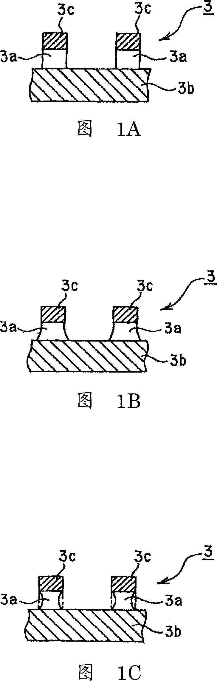
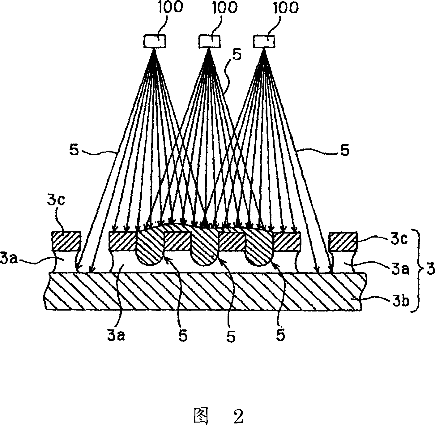
An etching device and an etching technology, which are applied in chemical/electrolytic methods to remove conductive materials, electrical components, printed circuit liquid treatment, etc., can solve the deviation of the width and cross-sectional shape of the conductor pattern 3a, difficulty in etching the conductor pattern 3a, and difficulty in etching Conductor patterns and other issues, to achieve the effect of eliminating deflection, uniform etching speed, and realizing narrow pitch

Active Publication Date: 2007-07-18
DEXERIALS CORP
View PDF3 Cites 3 Cited by
  • Summary
  • Abstract
  • Description
  • Claims
  • Application Information

AI Technical Summary

Problems solved by technology

[0008] In the method of performing etching using the above-mentioned etching apparatus shown in FIG. The weight of the etchant 5 on the upper surface of the flexible wiring substrate 3 makes the flexible wiring substrate 3 deflect, and the etchant 5 cannot contact the deflected part at a normal spray angle, and, since Since the etchant 5 remains on the bent portion, new etchant 5 cannot contact the bent portion, and it is difficult to etch the miniaturized conductor pattern 3a with high precision.
[0009] In addition, even if the etchant 5 is sprayed only on the lower surface side of the flexible wiring substrate 3, the etchant 5 does not come into contact with the portion deflected by the spray pressure of the sprayed etchant 5 at a normal spray angle. , therefore, it becomes difficult to etch the miniaturized conductor pattern 3a with high precision.
[0010] The problem of the remaining solution of such etching solution 5 on the substrate 3 for flexible wiring and the spraying angle of the etching solution 5 to the substrate 3 for flexible wiring is that: on the substrate 3 for flexible wiring, the problem shown in FIG. 1C is generated. The portion of the conductor pattern 3a that is etched quickly and the portion of the conductor pattern 3a that is etched slowly as shown in FIG.
[0012] However, it is difficult to make the etching rate uniform over the entire surface of the flexible wiring substrate 3. For example, even if the flexible wiring substrate 3 does not bend, due to the characteristics of the spray nozzle 100, the spray etching The liquid 5 spreads into a fan shape or a cone shape, and the injection pressure on the flexible wiring substrate 3 is not uniform, and the deviation of the width and cross-sectional shape of the etched conductor pattern 3a cannot be fundamentally eliminated.

Method used


Image

  • Etching device and etching method
  • Etching device and etching method
  • Etching device and etching method

Examples


Embodiment Construction

[0030] The preferred embodiments of the etching apparatus and etching method of the present invention will be described below with reference to the accompanying drawings.

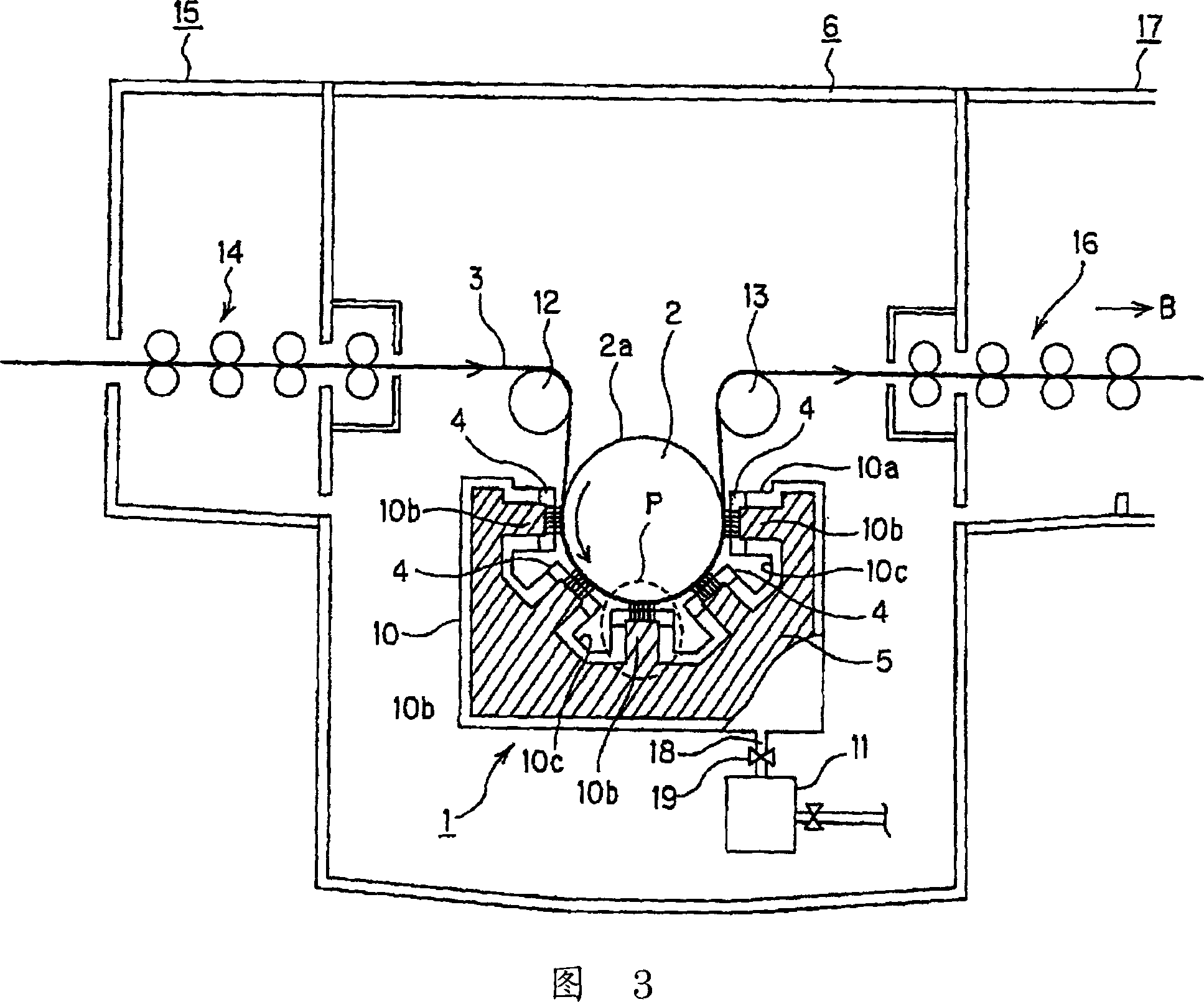
[0031] As shown in FIGS. 3 and 4 , the etching device 1 of the present invention is a device in which a shower head 4 is arranged close to a substrate 3 for flexible wiring wound on the outer peripheral surface of a drum 2 , and the flexible wiring from the shower head 4 The etchant 5 is sprayed in a straight line to the substrate 3 for wiring.

[0032] This etching device 1 is used for the etching process in each process of the metal surface etching method for forming a conductive pattern on the flexible wiring substrate 3, and is installed in an etching system configured by connecting processing chambers for performing each process. Room 6.

[0033] As shown in FIGS. 3 and 4 , the etching apparatus 1 includes a drum 2 , a container 10 , a shower head 4 , a pump 11 , and the like.

[0034] The drum 2 is ...


PUM


Abstract

An etching device for forming a conductor pattern by applying etching to a wiring board. The etching device comprises a drum, a chamber, and nozzle heads. The drum is formed to be rotatingly run in such a state that a flexible wiring board is wrapped around the surface of the drum. The chamber is a room for storing an etching liquid under a specified pressure. The nozzle heads are disposed at the upper part of the chamber in proximity to the surface of the drum, and formed to linearly jet the etching liquid pressurized in the chamber from nozzle holes against the surface of the drum.

Description

technical field [0001] The present invention relates to an etching device for forming a conductive pattern by etching a flexible wiring substrate, and to performing wet etching on the wiring substrate when forming a conductive pattern on the wiring substrate etching method. Background technique [0002] Conventionally, as shown in FIG. 1A, in flexible wiring boards used in COF or TAB mounting methods, the pitch of conductors 3a has been narrowed, and miniaturization of line / space ratio = 15 / 15 μm or less has been required. . Furthermore, as the frequency of signals increases, conductor resistance becomes an important factor, and not only the narrower pitch of the conductor pattern 3a is required, but also the cross-sectional shape of the conductor pattern 3a is required to be a perfect rectangle. [0003] Usually, when forming a flexible wiring board having a predetermined conductive pattern using the flexible wiring substrate 3, when the metal surface etching method is us...

Claims


Application Information

Patent Timeline
Patent Type & Authority Applications(China)
IPC IPC(8): H05K3/06
CPCH05K1/0393H05K2203/0746H05K3/068H05K3/0085H05K2203/1545
Inventor 玉野博基
Owner DEXERIALS CORP
Why Eureka
Try Eureka