Attachment of aircraft ribs to spars having variable geometry

a technology of wing ribs and wing spars, which is applied in the direction of energy-efficient board measures, couplings, manufacturing tools, etc., can solve the problems of affecting the aerodynamic performance of the wing, the transmission of stresses to the wing ribs to which the spar is attached, etc., to reduce or prevent the moment or twisting action of the tubular spar, the effect of isolating the ribs

Active Publication Date: 2016-05-24
THE BOEING CO
View PDF25 Cites 2 Cited by
  • Summary
  • Abstract
  • Description
  • Claims
  • Application Information

AI Technical Summary

Benefits of technology

[0009]The disclosed embodiments provide a method and a joint for attaching aircraft wing ribs or similar components to a tubular spar that varies in cross sectional shape during flight due to its composite laminate construction configuration and / or to changes in its internal pressurization. The method and attachment joint employ pivotal connections strategically located about the circumference of the tubular spar which allow relative motion between the tubular spar and the ribs, thereby isolating the ribs from stresses caused by cross sectional deformation of the spar. The pivotal connections include pivot pins located at the points of inflection of the changing cross sectional shape of the spar. Locating the pivot pins at the inflection points may substantially eliminate induced radial deflection of the tubular spar into the rib. The pivotal connections may also reduce or prevent a moment or twisting action of the tubular spar from being induced into the rib.

Problems solved by technology

Spar deformation caused by this cyclical gas pressurization may result in the transmission of stresses to wing ribs to which the spar may be fixedly attached.
These transmitted stresses may alter the shape of the rib and thus the overall shape of the airfoil, thereby affecting the aerodynamic performance of the wing.

Method used


Image

  • Attachment of aircraft ribs to spars having variable geometry
  • Attachment of aircraft ribs to spars having variable geometry
  • Attachment of aircraft ribs to spars having variable geometry

Examples


Embodiment Construction

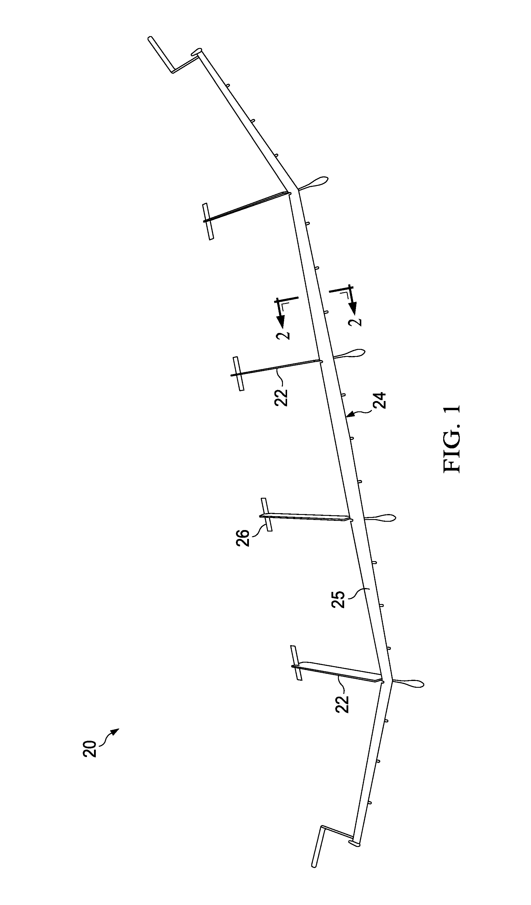
[0031]Referring first to FIG. 1, a high altitude, long endurance aircraft (HALE) 20, comprises a primary airfoil 24 in the form a main wing 25 attached to multiple spaced apart fuselages 22 each having a horizontal stabilizer 26. Although not shown in FIG. 1, the aircraft 20 may include solar panels for generating electricity to drive electric propulsion motors during daytime flight, and one or more fuel cells which drive the propulsion motors at night using gaseous fuels such as hydrogen and oxygen that are stored within the wing 25. The HALE aircraft 20 is merely illustrative of a wide range of aircraft that may employ features of the disclosed embodiments.

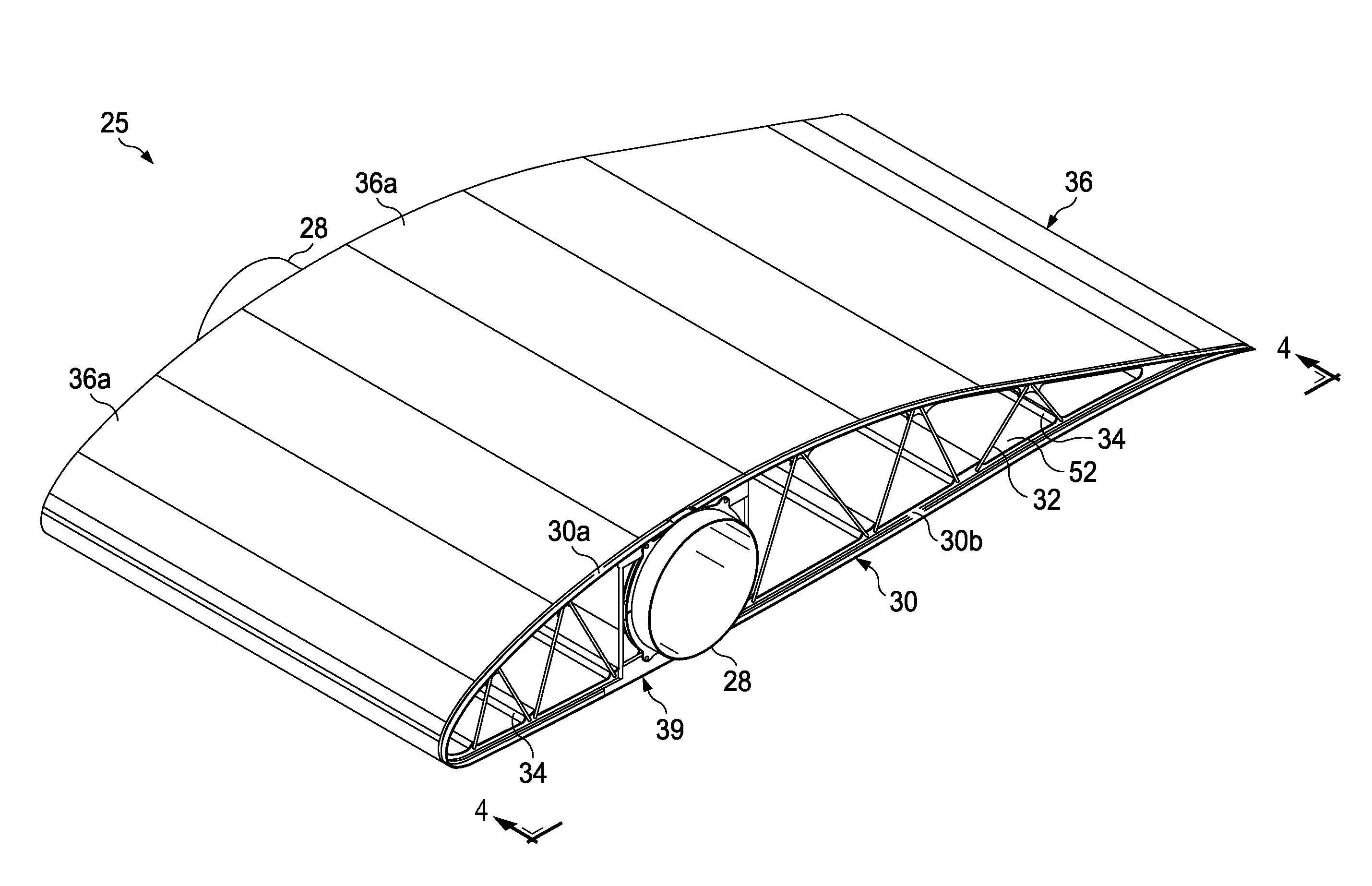
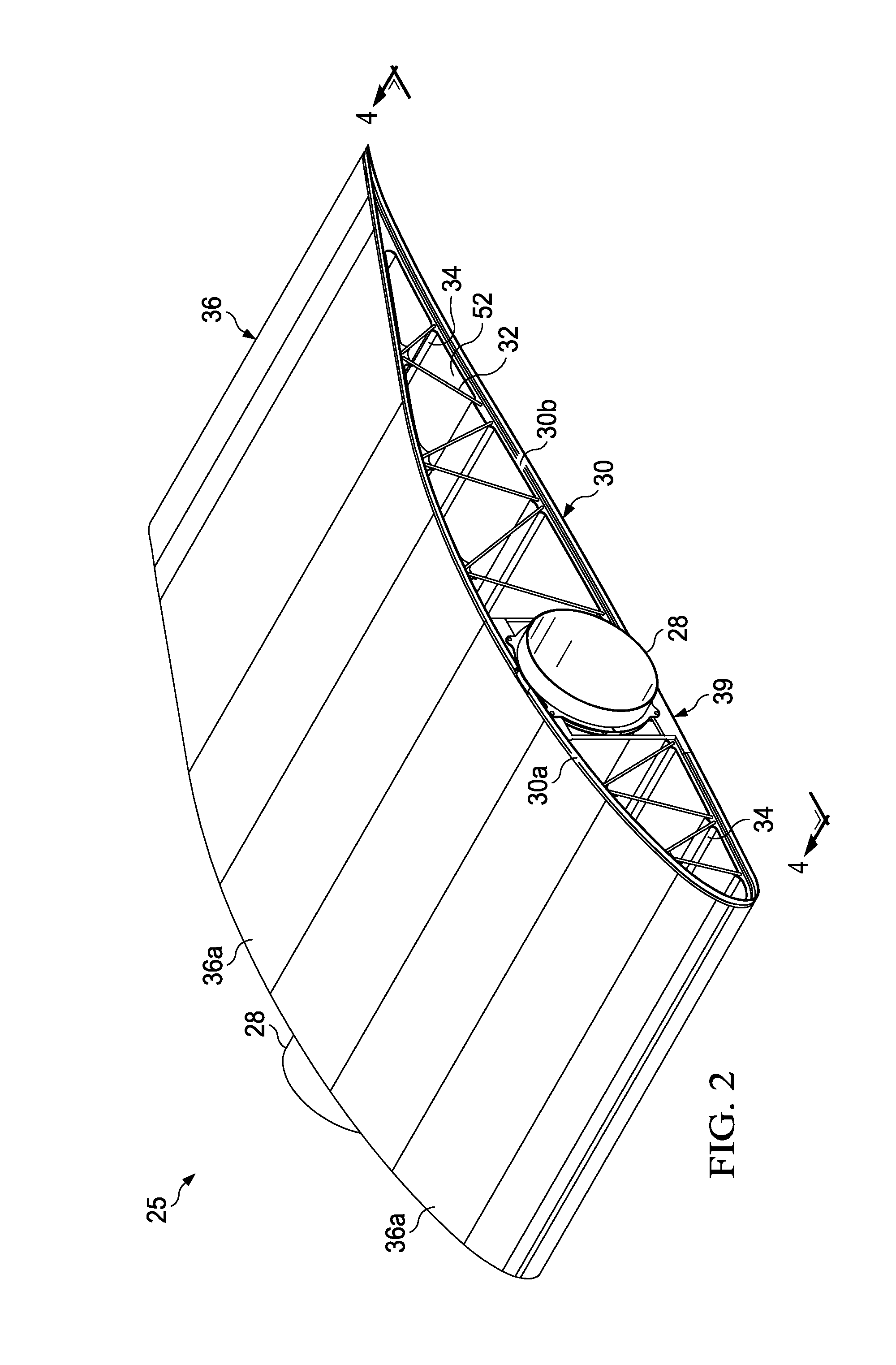
[0032]Referring to FIG. 2, the wing 25 may comprise a deformable tubular member such as a tubular wing spar 28 attached by joints 39 to each of a plurality of substantially non-deformable structures, such as spaced apart ribs 30. Each of the ribs 30 may be stiffened by struts 32 arranged in a truss pattern between upper and lowe...


PUM

PropertyMeasurementUnit
shapeaaaaaaaaaa
circumferenceaaaaaaaaaa
radial stiffnessaaaaaaaaaa

Abstract

An aircraft wing includes a rib attached by a joint to a tubular spar that varies in cross sectional shape during flight. The joint includes a ring attached to the tubular spar, and pivot pins connecting the ring with the rib. The pivot pins allow relative movement between the rib and the tubular spar as the tubular spar varies in cross sectional shape.

Description

STATEMENT REGARDING FEDERALLY SPONSORED RESEARCH OR DEVELOPMENT[0001]This invention was made with U.S. Government support under Agreement No. HR0011-10-9-0010, awarded by the Defense Advanced Research Projects Agency (DARPA). The U.S. Government has certain rights in the invention.CROSS REFERENCE TO RELATED APPLICATIONS[0002]This application is related to U.S. patent application Ser. No. 13 / 276,750 filed Oct. 19, 2011, the entire disclosure of which is incorporated by reference herein.BACKGROUND INFORMATION[0003]1. Field[0004]This disclosure generally relates to construction of airfoils such as aircraft wings, and deals more particularly with attachment of wing ribs to tubular wing spars having variable cross sectional geometries.[0005]2. Background[0006]High altitude, long endurance (HALE) solar powered aircraft have been designed that will remain aloft continuously for extended periods. During the day, on-board solar arrays generate electricity that is used to power electric propu...

Claims


Application Information

Patent Timeline
Patent Type & Authority Patents(United States)
IPC IPC(8): B64C3/18B64C3/34
CPCB64C3/185B64C3/187B64C3/34B64D2211/00Y10T29/49826Y10T403/32861Y02T50/50
Inventor KRUSE, JOHN SCOTTFOGARTY, JOHN HERSHEY
Owner THE BOEING CO
Why Eureka
Try Eureka