
Auxiliary forming positioning cold heading structure

An auxiliary forming and cold heading technology, which is applied in the direction of manufacturing tools, forging presses, forging/pressing/hammer devices, etc., can solve problems such as uneven material flow, achieve the effects of convenient modification, improve position accuracy, and improve contact quality

Pending Publication Date: 2020-09-22
厦门金波贵金属制品有限公司
View PDF0 Cites 2 Cited by
  • Summary
  • Abstract
  • Description
  • Claims
  • Application Information

AI Technical Summary

Problems solved by technology

[0002] Using a general-purpose bimetallic composite contact cold heading machine for upsetting contacts, due to the inherent characteristics of wire shear and the influence of the bonding position of the two metals, the material flow during contact forming is uneven.

Method used


Image

  • Auxiliary forming positioning cold heading structure
  • Auxiliary forming positioning cold heading structure
  • Auxiliary forming positioning cold heading structure

Examples


Embodiment Construction

[0024] The proprietary technology will be further described in conjunction with the accompanying drawings and specific embodiments.

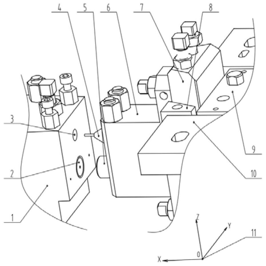
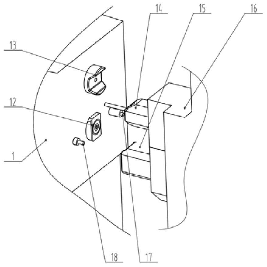
[0025] Such as figure 2 As shown, a cold heading structure for auxiliary forming and positioning mainly includes a fixed base part and a moving slider part.

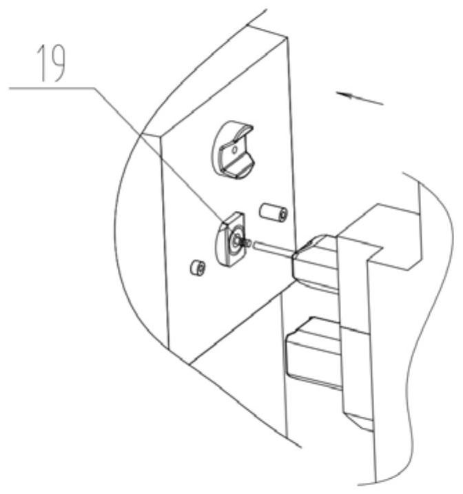
[0026] The fixed base part is mainly composed of a fixed base 1, a V-shaped fixed platform 12, and a Z-direction correction insert 13 and the like. Compared with the general cold heading structure, the V-shaped fixed table 12 is the figure 1 The shape of the fixed table 2 shown in Fig. 5-1 is redesigned into the shape shown in Fig. 5-1, and the installation and positioning straight surface on the fixed base 1 and the engagement with the V-shaped punch 15 shown in Fig. 5-4 are added. 60° angled convex engagement ramp. Then the original general cold heading structure figure 1 A new Z-direction correction insert 13 is redesigned at the position of the fixed seat avoidance hole 3 on the f...


PUM

PropertyMeasurementUnit
Opening angleaaaaaaaaaa

Abstract

The invention provides an auxiliary forming positioning cold heading structure. The structure is used for solving the problem that due to uneven flowing of a material during cold heading forming, during forming of a forming punch pin, deviation is generated, and coaxiality of a contact is affected. According to the structure, during closing of heading equipment, through a matched slope, positionsof the forming punch pin and a fixed table are subjected to positioning correcting in the Z direction and the Y direction, the influence that due to material uneven flowing, a movable sliding block deflects towards the sliding gap can be avoided, and the forming size precision of the contact can be improved.

Description

technical field [0001] The invention belongs to the field of metal cold heading forming, in particular to a cold heading structure for auxiliary forming and positioning. Background technique [0002] Using a general-purpose bimetallic composite contact cold heading machine for contact heading, due to the inherent characteristics of wire shear and the influence of the bonding position of the two metals, the material flow during contact forming is uneven. In addition, common cold heading structures such as figure 1 As shown, the fixed table 2 installed on the fixed base 1 and the forming punch 5 installed on the cross 6 will act on the forming punch by the lateral force generated by the uneven flow of the material when the contact is finally cold-headed 5, so that the forming punch has a tendency to deflect sideways. Because the forming punch 5 is fixed on the cross 6, the cross 6 is tightly connected with the movable slider 7, and the movable slider 7 and the Z-direction sl...

Claims


Application Information

Patent Timeline
IPC IPC(8): B21J5/00B21J5/06B21J9/02B21J13/00
CPCB21J5/004B21J5/06B21J9/02B21J13/00
Inventor 黄雄斌王金龙郑东风毛晓辉刘九龙
Owner 厦门金波贵金属制品有限公司
Learn More