Wiper control device

a control device and control device technology, applied in vehicle maintenance, vehicle cleaning, transportation and packaging, etc., to achieve the effect of preventing the rotation of the output shaft due to external for

Active Publication Date: 2019-08-29
DENSO CORP
View PDF4 Cites 2 Cited by
  • Summary
  • Abstract
  • Description
  • Claims
  • Application Information

AI Technical Summary

Benefits of technology

The invention is aimed at providing a wiper control device that can self-lock to prevent the wiper arm from deflection due to obstacles on the windshield glass. The device uses a rotational angle detection unit to monitor the changes in the motor's output shaft when the wiping operation is stopped. When the change in rotational angle reaches a predetermined value, self-locking is initiated. The device also includes a mechanism to stop the wiper motor when the wiping operation is stopped due to an obstacle. This mechanism helps prevent the wiper blade from being repelled by the deflection of the wiper arm. Additionally, when the rotational angle of the output shaft changes due to external force, the device controls the rotation of the output sh shaft to cancel out the change. This prevents the rotation of the output sh sh without adding a separate mechanism for mechanically constraining the output sh.

Problems solved by technology

However, in many cases, the wiper apparatus that operates the wiper blade on the driver's seat side and the wiper blade on the passenger's seat side with separate and independent motors does not have the link mechanism between the wiper arm and the wiper motor.

Method used


Image

  • Wiper control device
  • Wiper control device
  • Wiper control device

Examples


Embodiment Construction

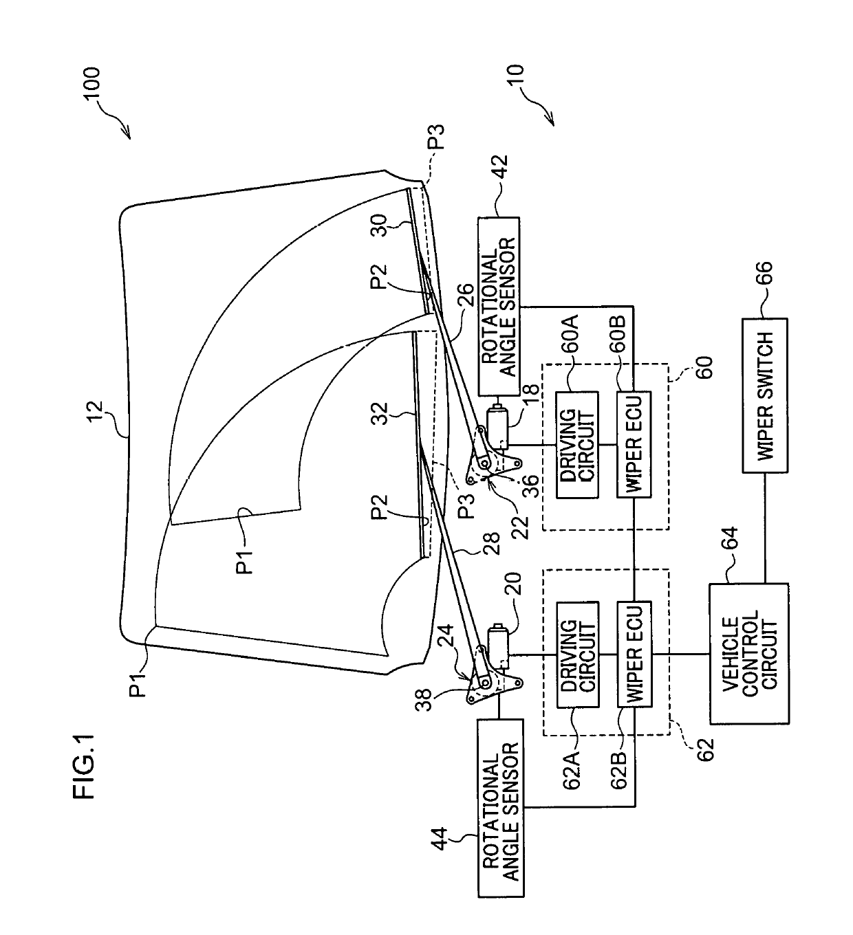
[0026]FIG. 1 is a schematic diagram showing a configuration of a wiper apparatus 100 including a wiper control device 10 according to the present embodiment. As an example, the wiper apparatus 100 is a tandem wiper apparatus including a left wiper apparatus 14 on the left (passenger's seat side) of a lower part of a windshield glass 12 of a right-hand drive vehicle, and a right wiper apparatus 16 on the right (driver's seat side) of a lower part of the windshield glass 12 of the vehicle. The left and the right in the present embodiment are the left and the right as seen from the vehicle interior.

[0027]The left wiper apparatus 14 and the right wiper apparatus 16 include wiper motors 18 and 20, deceleration mechanisms 22 and 24, wiper arms 26 and 28, and wiper blades 30 and 32, respectively. The wiper motors 18 and 20 are provided on the lower left side and the lower right side of the windshield glass 12, respectively.

[0028]In the left wiper apparatus 14 and the right wiper apparatus ...


PUM


Abstract

A wiper control circuit stops the supply of power for rotating a wiper motor in a case in which a wiper blade is stopped before a storage position. In a case in which the amount of change in a rotational angle of an output shaft before and after stopping the supply of power for rotating the wiper motor, which is detected by a rotational angle sensor, has reached a predetermined range, the wiper control circuit performs self-locking to prevent the rotation of the output shaft in a state after the supply of power is stopped.

Description

TECHNICAL FIELD[0001]The present invention relates to a wiper control device.BACKGROUND ART[0002]A wiper apparatus that operates a wiper blade on a driver's seat side and a wiper blade on a passenger's seat side with one wiper motor has a link mechanism for transmitting the rotational force of the wiper motor to a wiper arm. In a case in which external force due to a traveling wind or the like of a vehicle acts on a wiper blade or a wiper arm, the link mechanism also has a function of suppressing the wiper blade from moving to an unintended position by the external force.[0003]However, in many cases, the wiper apparatus that operates the wiper blade on the driver's seat side and the wiper blade on the passenger's seat side with separate and independent motors does not have the link mechanism between the wiper arm and the wiper motor. In such a wiper apparatus, when the wiper blade receives the external force due to the traveling wind or the like of the vehicle, the probability that ...

Claims


Application Information

Patent Timeline
Patent Type & Authority Applications(United States)
IPC IPC(8): B60S1/08
CPCB60S1/08
Inventor IJIMA, HIROTO
Owner DENSO CORP
Why Eureka
Try Eureka