
Distribution intermediate method and intermediate system

A distributed, one-line technology, applied in radio relay systems, diversity/multi-antenna systems, transmission systems, etc., can solve problems such as occupying time periods, reducing the average data communication rate of relay stations, and reducing

Active Publication Date: 2012-08-08
XFUSION DIGITAL TECH CO LTD
View PDF0 Cites 0 Cited by
  • Summary
  • Abstract
  • Description
  • Claims
  • Application Information

AI Technical Summary

Problems solved by technology

[0011] 1. Each transfer station between BS and SS / MSS occupies different frequency bands; its disadvantages are: the spectrum demand is relatively wide, and the spectrum is a scarce resource for operators, so more spectrum resources are wasted
[0012] 2. Each transfer station between BS and SS / MSS uses the same frequency band, but occupies different time periods; its disadvantage is that although the spectrum demand is small, for the user station, since each transfer station must work in time, reducing The average data communication rate of each transfer station is increased, and the throughput of the user station is limited, or even decreased.

Method used


Image

  • Distribution intermediate method and intermediate system
  • Distribution intermediate method and intermediate system
  • Distribution intermediate method and intermediate system

Examples


Embodiment Construction

[0076] The present invention is further elaborated below in conjunction with accompanying drawing and embodiment:

[0077] Such as figure 2 As shown, each node in the mutual aid node group can communicate with the destination node, and the communication target of the mutual aid node group is the destination node. There can be N nodes (N is a natural number) in the mutual aid node group, that is, node 1, node 2, ..., node N. For simplicity, only 4 nodes are given in the mutual aid node group in the figure as representatives.

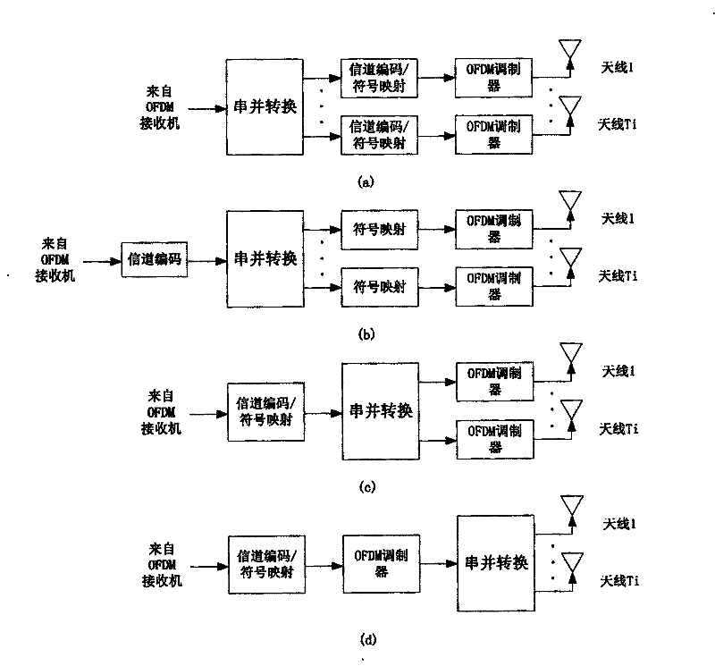
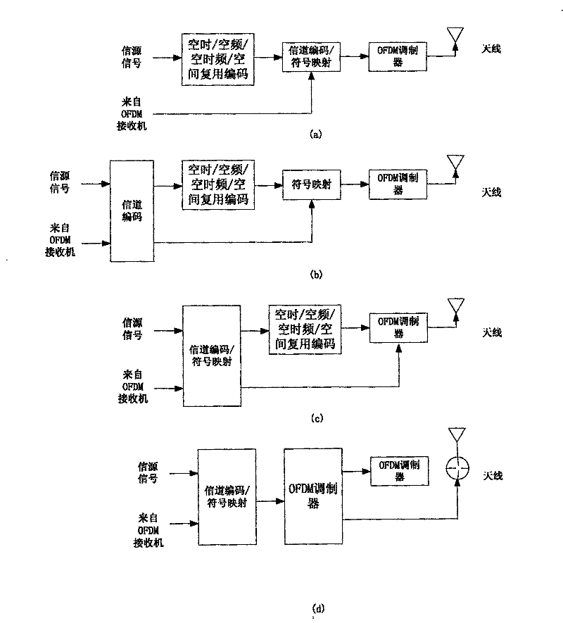
[0078] In the mutual aid node group, nodes 1, 2, . Assuming that node 1 becomes the source node, other nodes (node ​​2, ..., node N) in the mutual aid node group will all become transfer nodes to form a mutual aid transfer node group. The corresponding mutual aid transfer system model based on distributed multi-input multi-output coding is as follows: image 3 As shown, in addition to the direct communication channel, the communication channel between ...


PUM


Abstract

This invention discloses a distributed mutual transfer method and a system, in which, said method includes: a mutual node set transfers radio communication data of the mutual nodes to the objective node by the MIMU technology, said objective node receives and MIMU coding radio communication data from said mutual nodes, said system includes: a mutual node set and an objective node, in which, said mutual node set is composed of at least two mutual nodes and transfers radio communication data of the nodes to the objective node used in receiving and MIMU coding radio communication data from the mutual nodes.

Description

[technical field] [0001] The invention relates to the technical field of wireless communication, in particular to a distributed mutual aid transfer method and a transfer system. [Background technique] [0002] Theoretically, it has been proved that the use of multiple transmitting antennas can divide the wireless channel into multiple parallel narrowband channels, which has the potential to increase the channel bit transmission rate, and the research results show that the channel capacity increases linearly with the number of antennas. Compared with receive diversity and smart antennas, MIMO (Multiple Input Multiple Output) systems can not only provide diversity gain and array gain, but also increase system capacity by means of spatial multiplexing (SDM). [0003] BLAST (Bell LAboratory Space-Time architecture Bell Labs layered space-time structure) is a way to improve the effectiveness of bandwidth by using space multiplexing technology in wireless communication. It was fir...

Claims


Application Information

Patent Timeline
Patent Type & Authority Patents(China)
IPC IPC(8): H04L27/26H04B7/14H04B7/04
CPCH04L1/0045H04L2001/0097
Inventor 郑若滨
Owner XFUSION DIGITAL TECH CO LTD
Learn More