
Parallel distribution optical fibre raster temp. sensing method and its system

A distributed optical fiber and fiber grating technology, which is applied in the direction of using optical devices to transmit sensing components, thermometers, and thermometers with physical/chemical changes, can solve problems such as insufficient system reliability, small installation space, and operational complexity. , to achieve the effects of reducing product testing and maintenance costs, good consistency and interchangeability, and a large number of measurement points

Inactive Publication Date: 2007-07-18
福建迅捷光电科技有限公司
View PDF5 Cites 54 Cited by
  • Summary
  • Abstract
  • Description
  • Claims
  • Application Information

AI Technical Summary

Problems solved by technology

[0004] The patent application with publication number CN2599554Y is easily affected by electromagnetic interference during signal transmission, and the system reliability is insufficient; the patent application with publication number CN2599547Y introduces a photoelectric conversion system that requires battery power at the sensor end, the battery must be replaced regularly, and the explosion-proof performance is insufficient; The patent application with publication number CN1363828A adopts the same fiber grating series connection method, so it cannot accurately distinguish the sensing signal returned by each fiber grating. It can only judge whether there is an abnormal temperature detection point on each fiber grating string, and cannot obtain Accurate temperature value of each detection point; patents 200510021118.3 and 200410075518.8 use fiber gratings with different central wavelengths in series, although real-time temperature measurement of multiple detection points can be realized at the same time, and the signal transmission is anti-interference, but it is in a single channel Multiple grating sensors with different central wavelengths are connected in series on the optical fiber. The number of sensors that can be connected in series on a single optical fiber is restricted by the width of the light source and the temperature measurement range; The bending of the optical fiber must be greater than a certain bending radius. Due to the narrow installation space near the temperature measuring point of the power system, it is difficult to install the fiber grating sensor in series; at the same time, the fiber grating sensor with different central wavelengths cannot be interchanged and has no consistency. , which creates operational complexity and high costs in processing, calibration and user use

Method used


Image

  • Parallel distribution optical fibre raster temp. sensing method and its system
  • Parallel distribution optical fibre raster temp. sensing method and its system
  • Parallel distribution optical fibre raster temp. sensing method and its system

Examples


Embodiment Construction

[0041] The present invention will be further described below in conjunction with accompanying drawing:

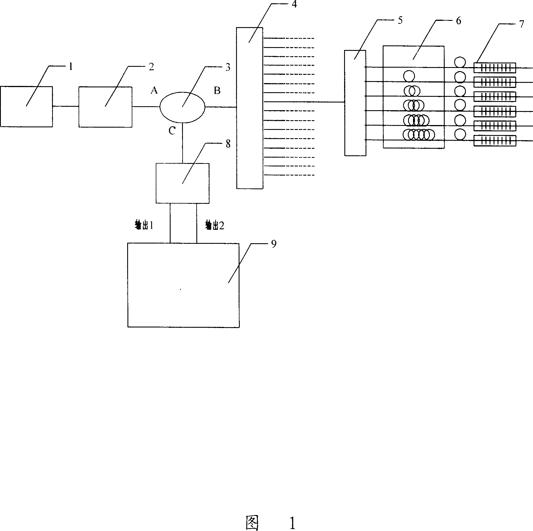
[0042] As shown in Figure 1, the SLD sends out a C-band optical signal with a spectral width of 40nm, which is amplified by the EDFA and then input to the A port of the circulator. The circulator outputs an optical signal from the B port to the common input port of the optical switch, and the optical switch switches the input signal to different Output port, each output port is connected with a fiber coupler, the fiber coupler divides the input optical signal to each output branch, and the optical signal output by each output branch is delayed by the fiber optic delay line group through the fiber grating sensor ( FBG) reflection. The FBG reflection signal passes through the fiber delay line group and then is combined by the fiber coupler, and then is input to the optical filter from the C port of the circulator after passing through the optical switch array and the circulat...


PUM


Abstract

The invention relates to full parallel distributing type optical fiber grating temperature sensing method and its system. The method includes the following steps: processing high speed modulation for the wide band light source to form pulse sequence with certain width and duty ratio; adopting parallel connection for the sensor each of which is corresponding with different time delay optical fiber; making the pulse light source signal enter into the sensor array by splitter; making each reflected light signal of the sensor enter into photo-electricity detecting unit by one and the same fiber coupler or optical circulator; receiving a series of pulsing signals in one light source modulating cycle each of which is corresponding with one sensor; gaining light signal center wavelength information by a special filter; detecting each of them to gain corresponding sensor temperature information.

Description

technical field [0001] The invention relates to the field of temperature measurement, and mainly refers to a fully parallel distributed optical fiber grating temperature sensing method and system thereof for monitoring ambient temperature changes by detecting changes in the wavelength of optical signals. Background technique [0002] The safety and maintenance of the power system has always been a major issue related to international people's livelihood. According to the analysis of a large number of electrical accidents, more than 90% of the accidents are caused by excessive temperature of equipment joints or contacts. The fire caused by overheating caused a large area of ​​factory buildings to be burned and forced to shut down, and the country lost more than one billion yuan every year. However, due to reasons such as electromagnetic interference and humidity, there is still a lack of effective means for temperature detection of power equipment. [0003] In the existing ...

Claims


Application Information

Patent Timeline
IPC IPC(8): G01K11/00G01K11/32G01D5/353G01D5/34G01D5/36G01K11/3206
Inventor 刘育梁张松伟陈云亮
Owner 福建迅捷光电科技有限公司
Learn More