
Plane wheel space displacement measuring system of landing gear lowering shock test

A technology of spatial displacement and measurement system, applied in measurement devices, instruments, etc., can solve problems such as installation difficulties

Inactive Publication Date: 2007-07-18
BEIHANG UNIV
View PDF0 Cites 15 Cited by
  • Summary
  • Abstract
  • Description
  • Claims
  • Application Information

AI Technical Summary

Problems solved by technology

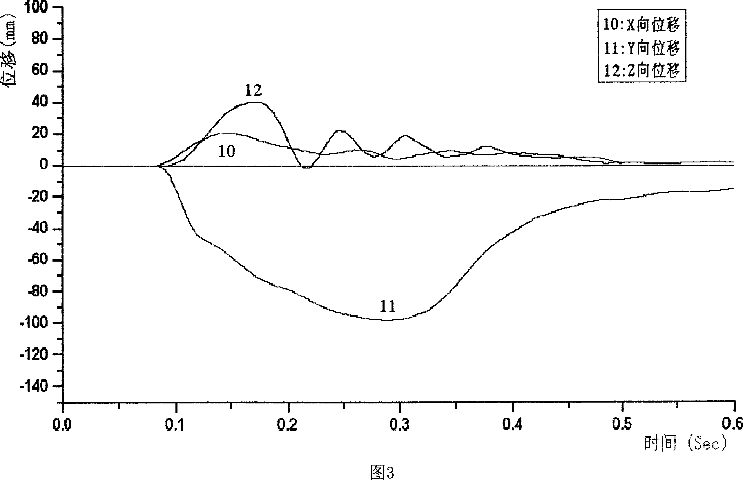
[0003] Since the impact of the landing gear on the ground occurs in a very short moment, the time for the impact force to reach the maximum value is only a few tenths of a second. A strong collision will cause severe vibration of the aircraft landing gear wheels, and generate dozens of vibrations in three directions in space. With a large range of elastic impact displacement of millimeters or even hundreds of millimeters, it is very difficult to install a large-scale spatial three-directional displacement test and recording device on the landing gear wheel that rotates at high speed and is mixed with strong elastic impact vibration
Therefore, at present, in China, it is still impossible to simultaneously measure and record the dynamic change process of the impact displacement of the aircraft wheel in three directions in space when the landing gear touches the ground.

Method used


Image

  • Plane wheel space displacement measuring system of landing gear lowering shock test
  • Plane wheel space displacement measuring system of landing gear lowering shock test
  • Plane wheel space displacement measuring system of landing gear lowering shock test

Examples


Embodiment Construction

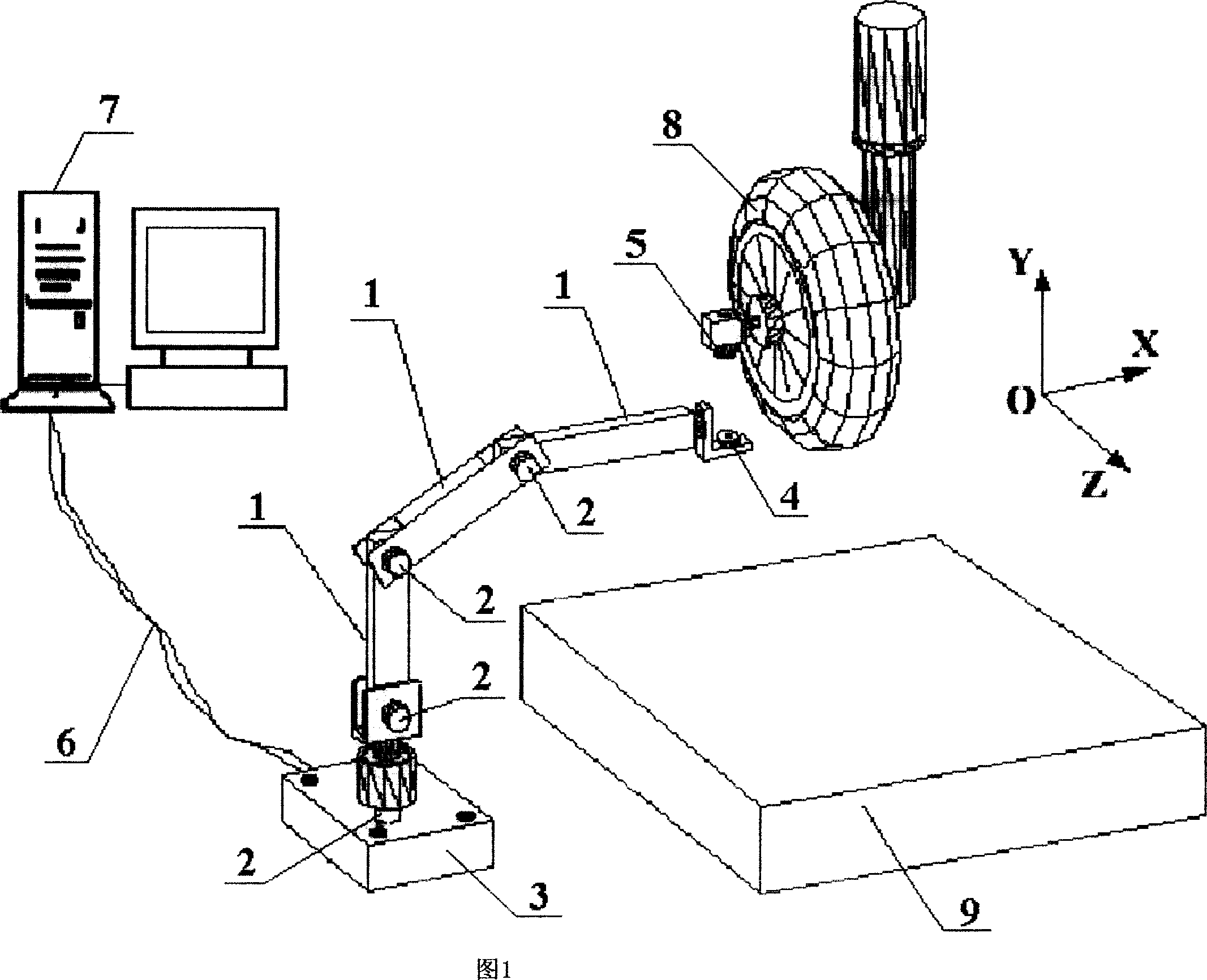
[0012] As shown in Figure 1, the present invention is made up of space positioning manipulator 1, angle sensor 2, bearing 3, magnetic attraction element 4 and 5 and computer 7, and three space positioning manipulator 1 is the form of series hinge, three articulated The shafts are all rotation angle sensors 2, and the fourth rotation angle sensor 2 is installed vertically on the top of the support 3. The upper end of the rotation axis is hinged with the lower end of the third space manipulator 1 connected in series. The computer 7 is connected, the magnetic attraction element 4 is connected with the free end of the mechanical arm 1 , and the magnetic attraction element 5 is fixed on the aircraft wheel 8 .

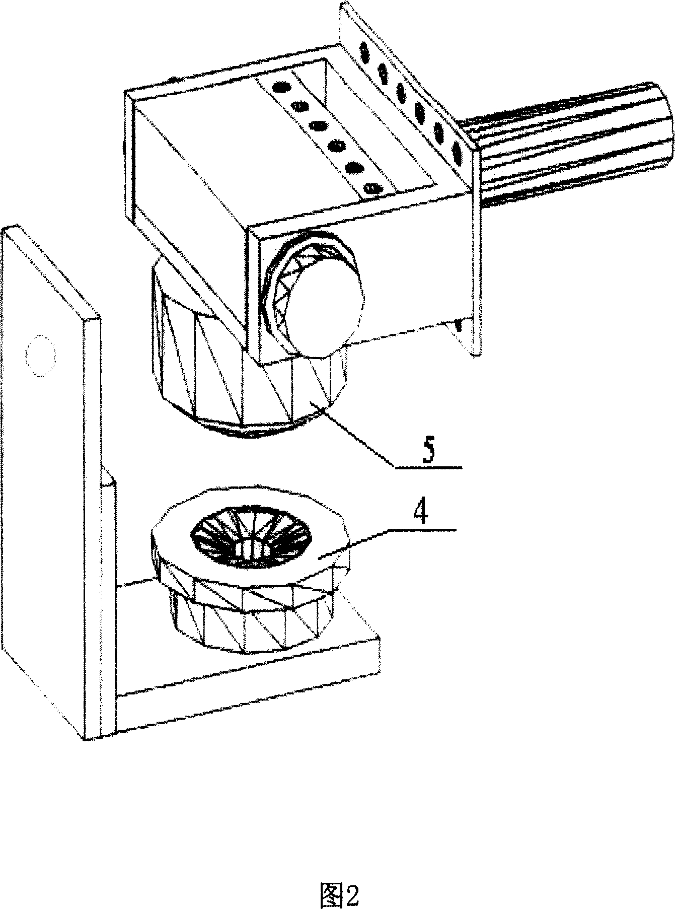
[0013] As shown in FIG. 2 , the magnetic attraction element 4 is a concave curved surface structure, the magnetic attraction element 5 is a convex curved surface structure, and the magnetic attraction elements 4 and 5 are strong magnetic attraction elements of NdFeB. In orde...


PUM


Abstract

The invention relates to undercarriage shock test airplane wheel space displacement measuring system. It is made up of three space locating machine arms, four corner transducers, support, two magnetic attracting components, and computer. The three space locating machine arms are connected with each other by connecting fitting on which three corner transducers are set. The forth one is set on the support. Each of them is connected with the computer by lead. One magnetic attracting component is connected with the free end of the third space locating machine arm. Another one is fixed on the principal axis of the airplane wheel. While measuring three directions displacement, the invention can ensure expensive undercarriage run normally after shock test without drilling to set displacement transducer and destroying its structure and strength.

Description

technical field [0001] The invention relates to a space displacement measurement system of an aircraft wheel for a landing gear drop test, which is used for dynamically measuring the impact displacement tracks of the aircraft wheel in three directions in space when the landing gear touches the ground in the landing gear drop test. Background technique [0002] At the moment when the aircraft hits the ground, the dynamic variation of the impact displacement of the landing gear wheel in three directions in space is the key parameter for studying the impact load and energy absorption of the aircraft landing gear. The work of measuring and recording the dynamic change process of the impact displacement of the wheel in three directions at the moment of the aircraft landing has very important practical engineering significance for the safety design of the aircraft. [0003] Since the impact of the landing gear on the ground occurs in a very short moment, the time for the impact fo...

Claims


Application Information

Patent Timeline
Patent Type & Authority Applications(China)
IPC IPC(8): G01B21/02G01B21/04G01M7/00
Inventor 吴大方杨嘉陵高镇同赵寿根赵星
Owner BEIHANG UNIV
Learn More