
Composite membrane electrode of direct borohydride fuel cell

A fuel cell and borohydride technology, which is applied to fuel cell components, fuel cells, battery electrodes, etc., can solve the problems of low total utilization rate of battery fuel and unavailability of hydrogen, and achieve a simple and compact overall structure and reduced volume. , The effect of reducing the internal pressure of the battery

Inactive Publication Date: 2010-03-10
HARBIN INST OF TECH
View PDF4 Cites 0 Cited by
  • Summary
  • Abstract
  • Description
  • Claims
  • Application Information

AI Technical Summary

Problems solved by technology

[0004] A composite membrane electrode for direct borohydride fuel cells, which solves the problems of unusable hydrogen generated by hydrolysis of direct borohydride fuel cells and low total utilization of battery fuel

Method used


Image

  • Composite membrane electrode of direct borohydride fuel cell
  • Composite membrane electrode of direct borohydride fuel cell
  • Composite membrane electrode of direct borohydride fuel cell

Examples


specific Embodiment approach 1

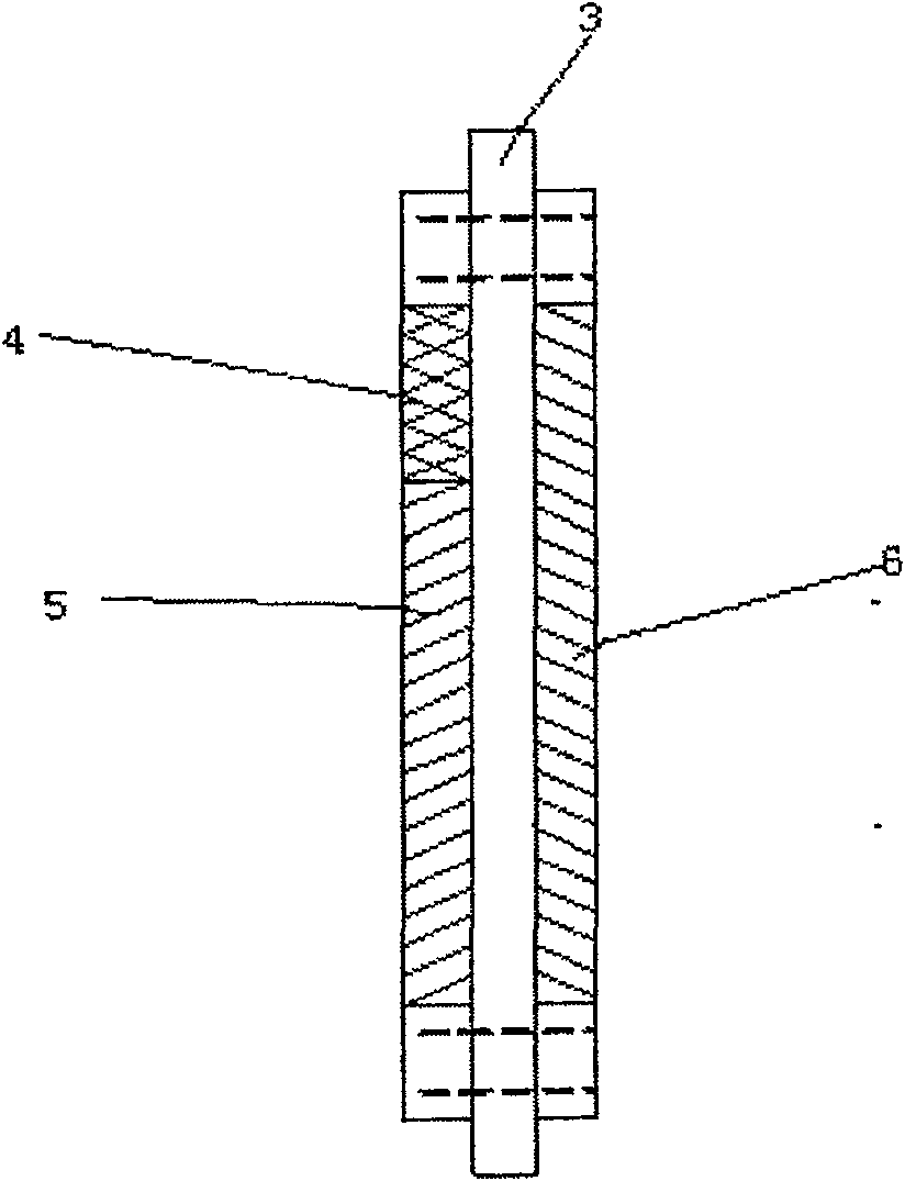
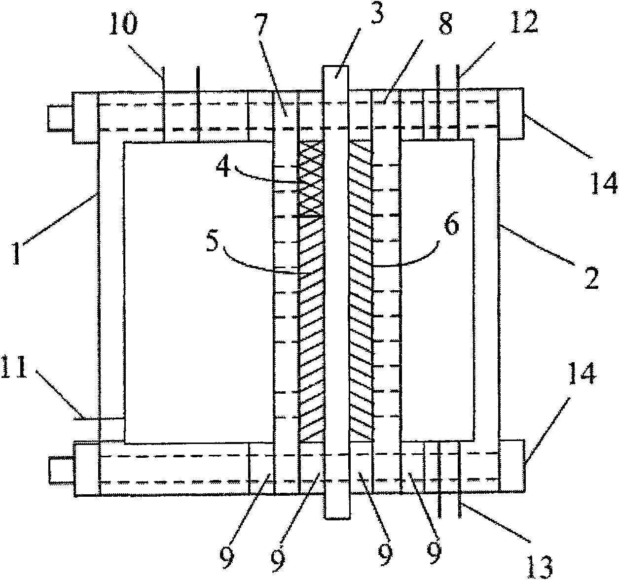
[0013] Embodiment 1: The composite membrane electrode of the direct borohydride fuel cell in this embodiment is composed of an anode, a cathode 6 and an electrolyte membrane 3. The anode and the cathode 6 are respectively located on both sides of the electrolyte membrane 3 and parallel to the electrolyte membrane 3. The three Hot-pressed film-forming electrode; the anode is composed of a borohydride catalytic oxidation anode 5 and a hydrogen catalytic oxidation anode 4, the hydrogen catalytic oxidation anode 4 is located at the upper part of the anode, and the borohydride catalytic oxidation anode 5 is located at the lower part of the anode.

specific Embodiment approach 2

[0014] Embodiment two: the difference between this embodiment and embodiment one is: borohydride catalytic oxidation anode 5 is made of carbon paper and a catalyst sprayed on the carbon paper, and both the carbon paper and the catalyst carry out hydrophilic treatment; Directly adopt active ingredient porous structure, active ingredient powder particles or composed of active ingredient and carrier; the active ingredient is Pt, Au, Ni, Pd, Ag, Ir, Os, Sn, Mo, W, V, PtO, PtO 2 , NiO, NiO 2 , Ni(OH) 2 , PdO, PdO 2 , AgO, Ag 2 O, SnO 2 、MoO 2 、MoO 3 , WC, WO 2 、WO 3 , V 2 o 5 One or more of them, when there are two or more active components, the components are mixed in any proportion; the carrier is carbon powder and carbon nanotubes. Others are the same as in the first embodiment.

specific Embodiment approach 3

[0015] Specific embodiment three: the difference between this specific embodiment and specific embodiment two is: the catalyst does not directly adopt the porous structure of the active component without the carrier, wherein the active component is Pt, Au, Ni, Pd, Ag, Ir, Os, Sn, Mo, W, V, PtO, PtO 2 , NiO, NiO 2 , Ni(OH) 2 , PdO, PdO 2 , AgO, Ag 2 O, SnO 2 、MoO 2 、MoO 3 , WC, WO 2 、WO 3 , V 2 o 5 One or more of them; when there are two or more active ingredients, each component is mixed in any proportion. Others are the same as in the second embodiment.


PUM


Abstract

A composite membrane electrode of a direct borohydride fuel cell relates to a fuel cell membrane electrode. The composite membrane electrode solves the problems that the hydrogen produced by hydrolysis of the direct borohydride fuel cell can not be directly used and the overall utilization rate of the cell fuel is low. The composite membrane electrode of the direct borohydride fuel cell is composed of an anode, a cathode (6) and an electrolyte membrane (3). The anode and the cathode (6) are respectively arranged on two sides of the electrolyte membrane and parallel to the electrolyte membrane;the anode, the cathode and the electrolyte membrane are hot pressed to a membrane electrode; the anode is composed of a borohydride-radical catalytic oxide anode (5) which is arranged on the lower part of the anode and a hydrogen catalytic oxide anode (4) which is arranged on an upper part of the anode. The side reaction of the borohydride radical is unavoidable on the borohydride-radical catalytic oxide anode, and the hydrogen is produced and can continue to react as the fuel on the hydrogen catalytic oxide anode, which can improve the overall utilization rate of the fuel and causing the structure of the whole membrane electrode system to be more compact and safer.

Description

technical field [0001] The invention relates to a fuel cell composite membrane electrode. Background technique [0002] Due to the advantages of high efficiency, no pollution, wide range of fuel sources, simple structure and easy maintenance, fuel cells have good application prospects. Among fuel cells, proton exchange membrane fuel cell (PEMFC) is the most researched and relatively mature technology. Borohydride is rich in hydrogen, such as sodium borohydride has a hydrogen volume capacity of 113.56kg / m 3 , has been studied as a fuel for fuel cells. Borohydride is used in fuel cells in both indirect and direct ways. The indirect method is to first catalyze the hydrolysis of borohydride to generate hydrogen, which is used as the fuel of PEMFC, but this only uses half of the coulombic power of borohydride, because the hydrolysis process does not generate electricity, and 1mol of borohydride is hydrolyzed to produce 2mol of H 2 , Electrooxidation has 4mol electron transfer...

Claims


Application Information

Patent Timeline
Patent Type & Authority Patents(China)
IPC IPC(8): H01M8/10H01M8/02H01M4/86H01M4/90H01M8/1004
CPCY02E60/521Y02E60/50
Inventor 尹鸽平王广进邵玉艳王振波杜春雨程新群左朋建高云智
Owner HARBIN INST OF TECH
Learn More