Purification device and refrigerator using the same
A technology of purification device and refrigerator, applied in application, ice making, ice making, etc., can solve problems such as incomplete purification, and achieve the effect of maintaining dimensional accuracy, shortening distance, and being easy to manufacture
- Summary
- Abstract
- Description
- Claims
- Application Information
AI Technical Summary
Problems solved by technology
Method used
Image
Examples
no. 1 Embodiment
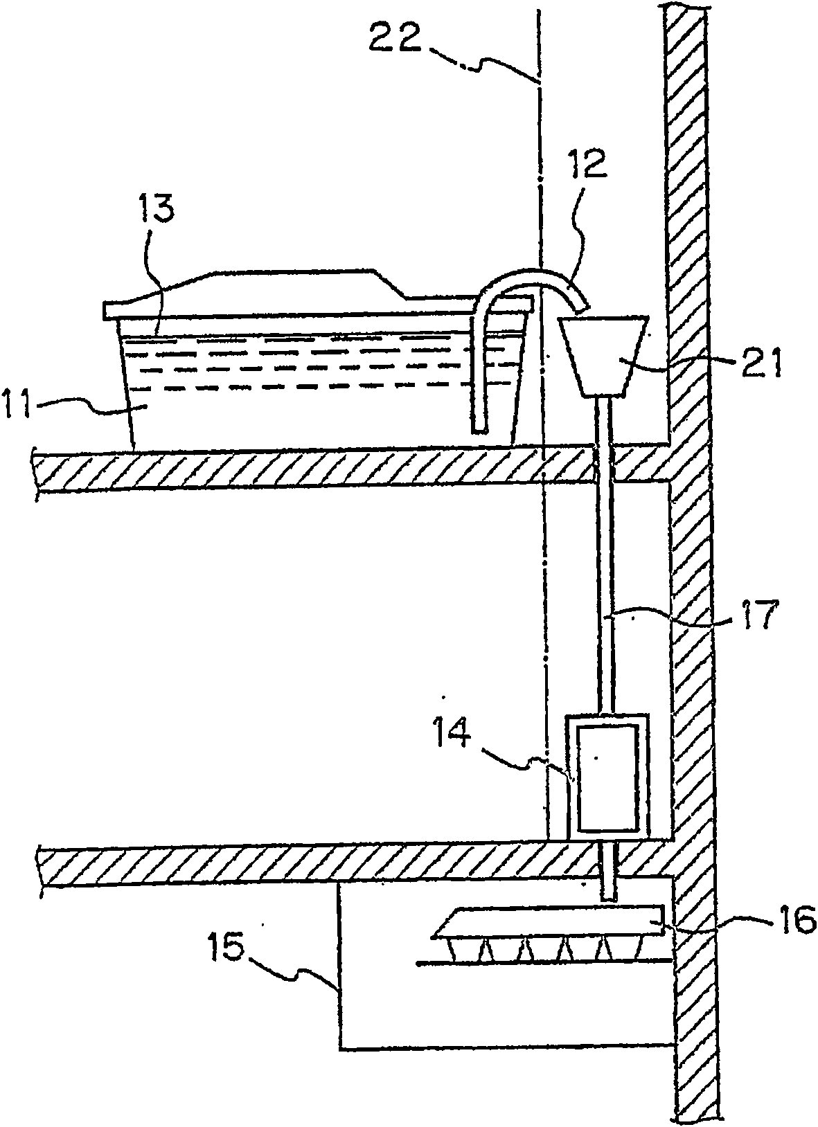
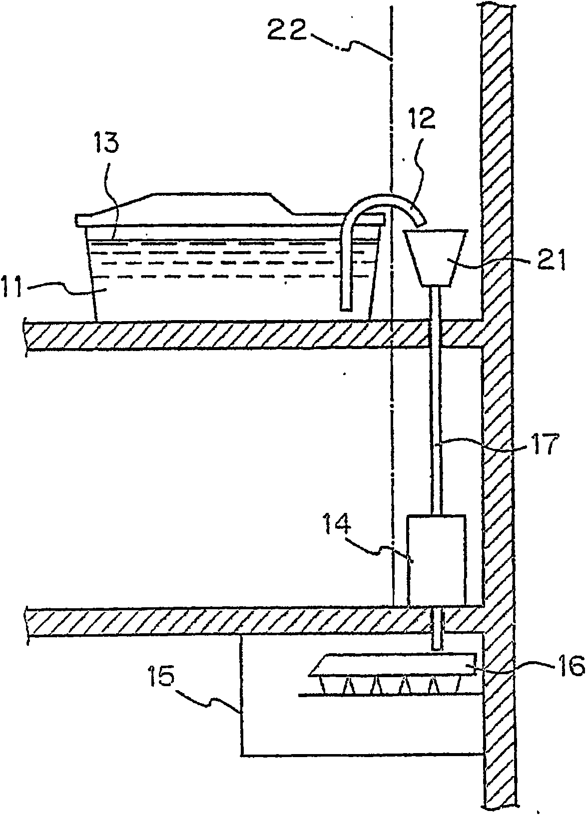
[0088] figure 1 The configuration of the ice making device in the refrigerator 100 according to the first embodiment of the present invention is shown. A water supply pipe 12 is disposed in a water supply tank 11 of the ice maker. The ice-making water 13 in the water supply tank 11 is exported from the water supply pipe 12 to the outside of the tank, and then is supplied to the ice-making tray 16 in the ice-making compartment 15 after passing through the purification device 14 outside the tank.
[0089] The water receiving body 21 is a part temporarily storing the ice-making water 13 sucked out by the pump (not shown) from the water supply tank 11 through the water supply pipe 12. 13 is supplied to the cleaning device 14 and the ice making chamber 15.
[0090]There is no particular limitation on the installation location of the suction pump for transferring the flow from the water supply tank 11 to the ice making compartment 15 . For example, the pump can be arranged on th...
no. 2 Embodiment
[0095] Refer below figure 2 , image 3 A refrigerator 100 according to a second embodiment of the present invention will be described.
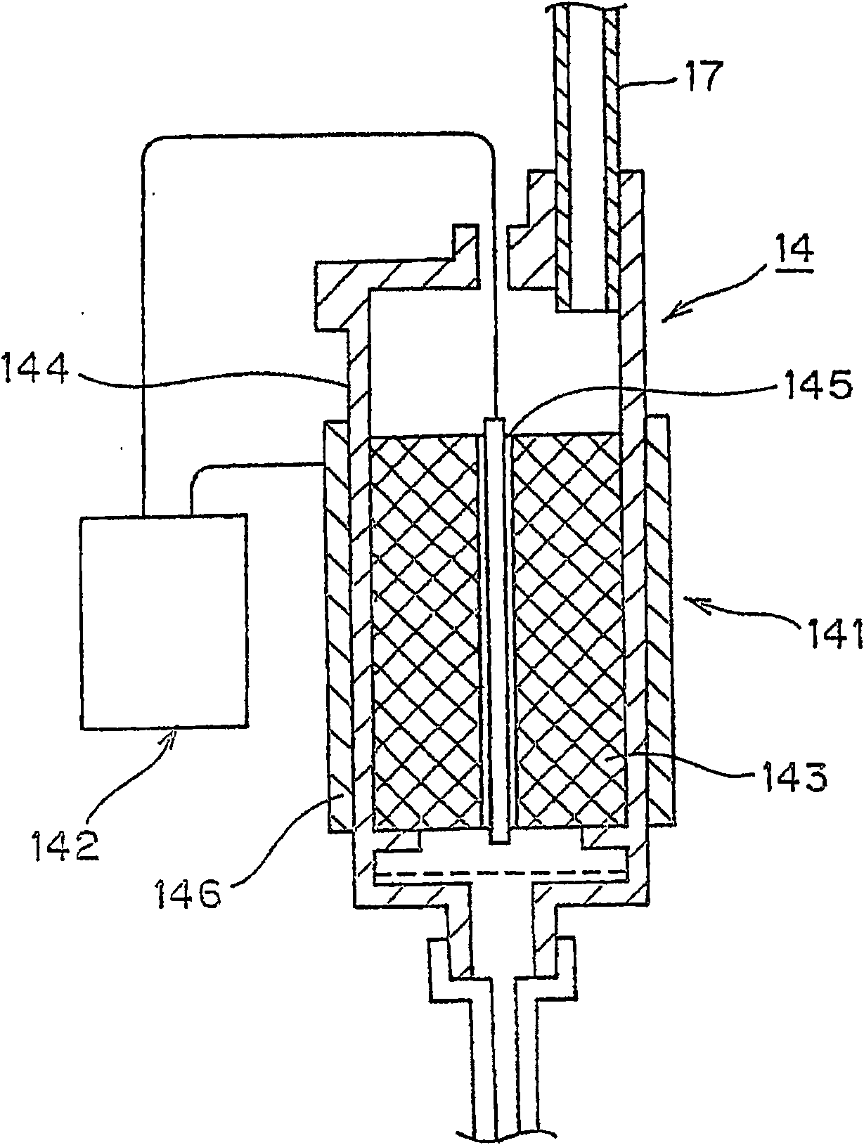
[0096] The second embodiment is characterized in that a discharge type photocatalyst filter is used in the purification device 14 provided outside the water supply tank 11 . In addition, the water 13 for ice making in the water supply tank 11 is supplied to the purification device 14, and the pipe route for supplying the water to the ice making chamber 15 after purification is the same as that of the first embodiment. However, the transfer pipe 17 from the water receiving body 21 to the purification device 14 is a throttle pipe, and the discharge pressure is increased after the flow rate is throttled, and the ice-making water 13 is supplied to the purification device 14 in a gas-liquid mixture.
[0097] Such as image 3 As shown, the purification device 14 , that is, the discharge-type photocatalyst filter, is composed of a photocatalyst ...
no. 3 Embodiment
[0103] Referring to Fig. 5 below, Image 6 A refrigerator according to a third embodiment of the present invention will be described.
[0104] Fig. 5 shows a cleaning device 14 used in the refrigerator of the third embodiment. The purification device 14 used in this embodiment is characterized in that the flow of the ice-making water 13 introduced into the purification device 14 from the pipette 17 has a spiral (vortex) structure. That is, the water guide port 147 is arranged on the upper part of the reaction container 144 along the horizontal tangential direction, and the ice-making water 14 flowing from the pipette 17 to the purification device 14 becomes a swirling vortex as shown by the arrow A, and flows into the ceramics in a spiral flow. Carrier 143. Additionally, other structures with figure 2 , image 3 The structure of the refrigerator of the second embodiment shown is the same. In addition, a configuration may be adopted in which the ice-making water 13 is sup...
PUM
| Property | Measurement | Unit |
|---|---|---|
| thickness | aaaaa | aaaaa |
Abstract
Description
Claims
Application Information
 - R&D
- Intellectual Property
- Life Sciences
- Materials
- Tech Scout
- Unparalleled Data Quality
- Higher Quality Content
- 60% Fewer Hallucinations
Browse by: Latest US Patents, China's latest patents, Technical Efficacy Thesaurus, Application Domain, Technology Topic, Popular Technical Reports.
© 2025 PatSnap. All rights reserved.Legal|Privacy policy|Modern Slavery Act Transparency Statement|Sitemap|About US| Contact US: help@patsnap.com


