
Differential pressure low-energy-consumption distillation method and equipment

A technology of energy consumption and rectification, applied in the field of rectification, can solve the problems of matching heat exchange between the top condenser and the column bottom reboiler, and the inability to realize thermal coupling, etc.

Active Publication Date: 2010-01-27
TIANJIN UNIV
View PDF3 Cites 0 Cited by
  • Summary
  • Abstract
  • Description
  • Claims
  • Application Information

AI Technical Summary

Problems solved by technology

Regardless of the design of pre-fractionation tower, intermediate side line heat exchange, side line distillation process or side line stripping process, for the main rectification column, since the temperature at the top of the column is higher than the temperature at the bottom of the column, that is, the temperature of the material at the top of the column after condensation is higher. It is higher than the temperature to be reached by the reboiler of the bottom material, so the matching heat exchange between the top condenser and the bottom reboiler cannot be simply performed, and complete thermal coupling cannot be achieved

Method used


Image

  • Differential pressure low-energy-consumption distillation method and equipment
  • Differential pressure low-energy-consumption distillation method and equipment
  • Differential pressure low-energy-consumption distillation method and equipment

Examples


Embodiment Construction

[0024] The technology and equipment provided by the present invention will be further described below in conjunction with the accompanying drawings.

[0025] The present invention is achieved through the following technical solutions:

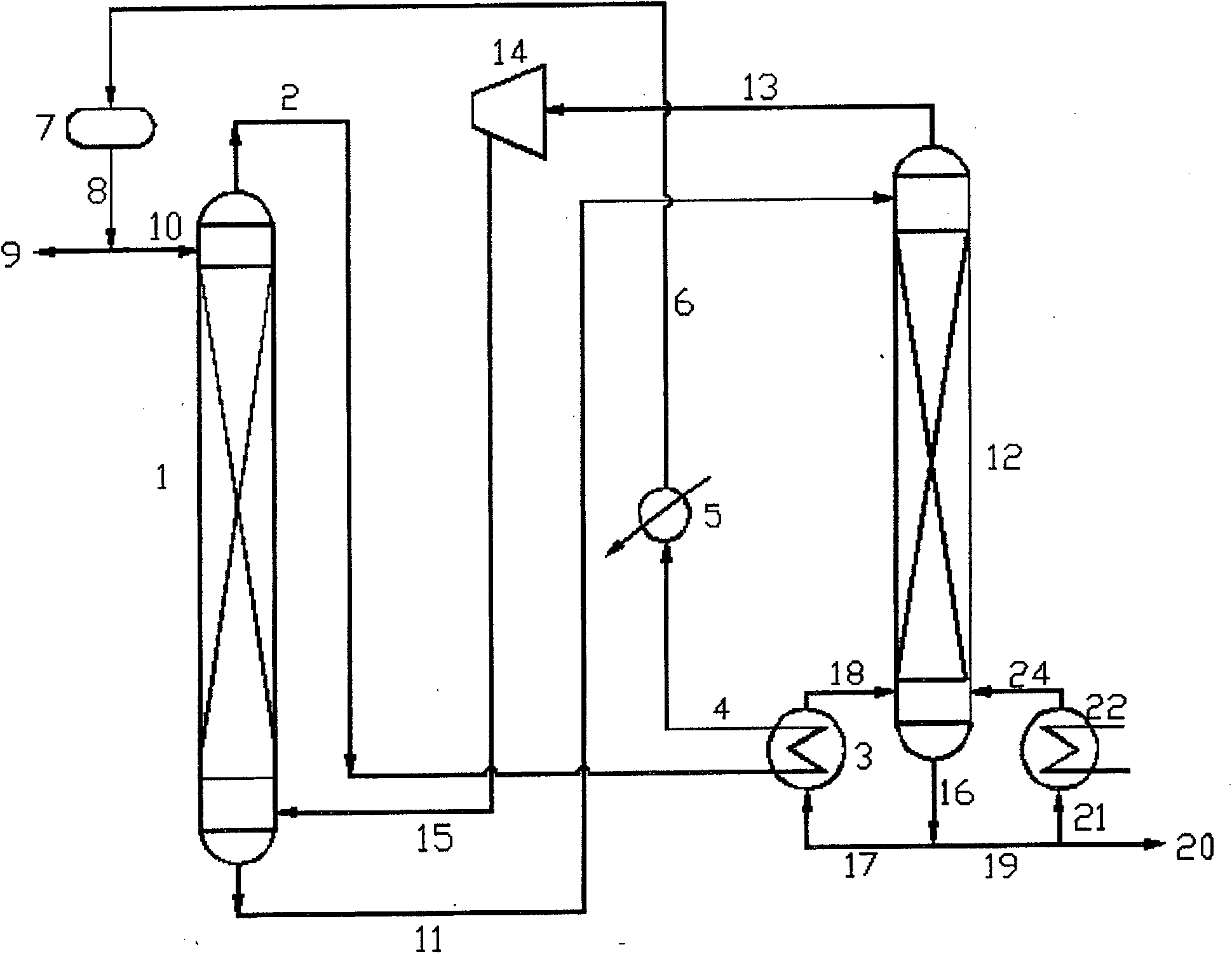
[0026] Such as figure 1 As shown, the liquid phase material at the bottom of the tower after being separated by the conventional separation tower section 1 enters the top of the decompression separation tower section 12 under pressure differential push; the steam 13 coming out of the top of the decompression separation tower section enters the conventional The bottom of the separation column section is used as rising steam 15; part of the liquid phase 16 from the bottom of the decompression separation column section can be extracted as a product 20, and the other part 17 is in the main reboiler 3 with the steam 2 from the top of the conventional separation column section Perform heat exchange to form the reboil steam 18 required at the bottom ...


PUM


Abstract

The present invention provides a rectifying method having differential pressure and lower energy consumption, and an apparatus, including a general knockout tower section, a underpressure knockout tower section, a main reboiler, a reflux accumulator and a compressor, wherein , a compressor is set between the underpressure knockout tower section and the general knockout tower section, the gas material tube on the top of the underpressure knockout tower section is connected to the inlet of the compressor, the outlet of the compressor is connected to the gas inlet ont the bottom of the general knockout tower section; gas material outlet of the general knockout tower section is connected to the heat medium inlet of the main reboiler, heating medium outlet is connected to the reflux accumulator of the general knockout tower section; the liquid outlet on the bottom of the general knockout tower section is connected to the liquid inlet of the underpressure knockout tower section; the liquid material outlet tube on the bottom of the underpressure knockout tower section is connected to the cooling medium inlet of the main reboiler, outlet of the cooling medium is connected to the inlet of the reboiler of the underpressure knockout tower section. The invention realises thermally coupled distillation, matching heat exchange. The minimum heat consumption is realised by differential pressure temperature reduction means, even the cool-heat load are fully matched, the consumption is zero. Ways to achieve the aim only is adding a compressor in the equipment, the dynamic consumption is lower than the original consumption.

Description

technical field [0001] The invention relates to the technical field of rectification, in particular to a rectification method and equipment with differential pressure and low energy consumption suitable for the processing process of high energy-consuming fine chemicals. Background technique [0002] Rectification is a widely used chemical separation unit operation, but the rectification process consumes a lot of energy, and improving the energy utilization rate of the rectification process has always been a research hotspot. [0003] In recent years, thermocouple rectification has attracted widespread attention because of its energy saving and equipment investment savings. The earliest thermocouple rectification was proposed by Petlyuk 50 years ago. The study found that thermocouple rectification can save energy by at least 30% compared with conventional distillation process, but it was difficult to industrialize due to the technical conditions at that time. In recent years...

Claims


Application Information

Patent Timeline
Patent Type & Authority Patents(China)
IPC IPC(8): B01D3/14
Inventor 李鑫钢罗铭芳李洪姜斌黄国强许长春许力强隋红孙津生陈宁
Owner TIANJIN UNIV
Learn More