Piping with fluid mixing region
A fluid mixing and piping technology, used in fluid mixers, mixers, gas/liquid distribution and storage, etc., can solve problems such as difficulty in completely preventing temperature interface changes, prevent thermal fatigue, promote mixing, reduce Effects of temperature changes
- Summary
- Abstract
- Description
- Claims
- Application Information
AI Technical Summary
Problems solved by technology
Method used
Image

Examples
no. 1 approach
[0074] Below, refer to figure 1 The first embodiment of the present invention will be described.
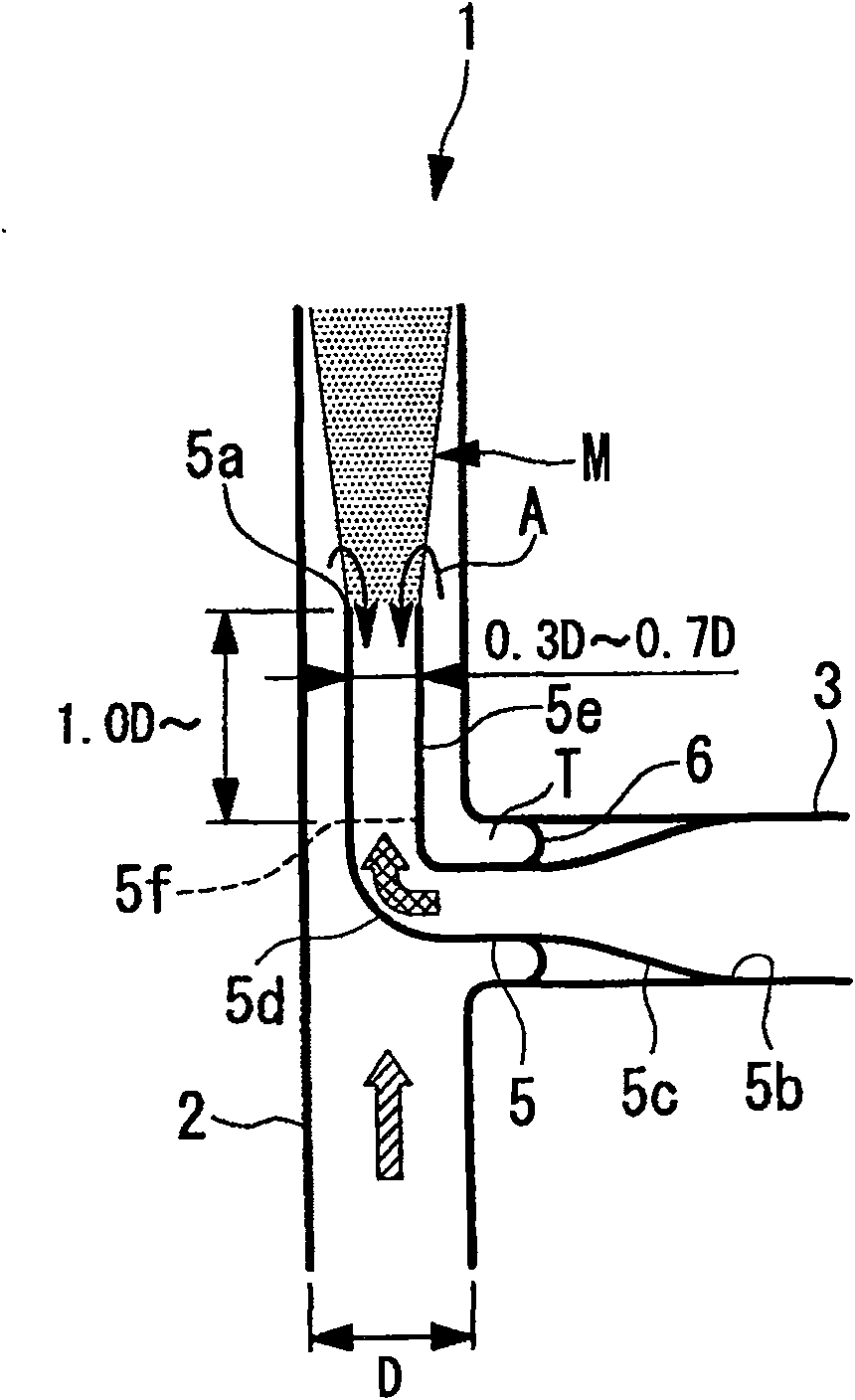
[0075] figure 1 A pipe 1 having a fluid mixing region M is shown.
[0076] The pipe 1 is composed of a main pipe (first pipe) 2 and a branch pipe (second pipe) 3 .
[0077] The main pipe 2 is made of metal with an inner diameter D, and high-temperature water (high-temperature fluid) flows from the bottom to the top in this figure.
[0078] The branch pipes 3 are connected in an orthogonal manner with respect to the outer wall of the main pipe 2 . The branch pipe 3 is made of metal, and low-temperature water (low-temperature fluid) having a temperature lower than that of the high-temperature water flowing through the main pipe 2 flows therein. The low-temperature water flowing in the branch pipe 3 flows from the right side to the left side in the drawing, passes through the reducer (inner pipe) 5 , and flows out into the main pipe 2 from the downstream end 5 a of the reducer...
no. 2 approach
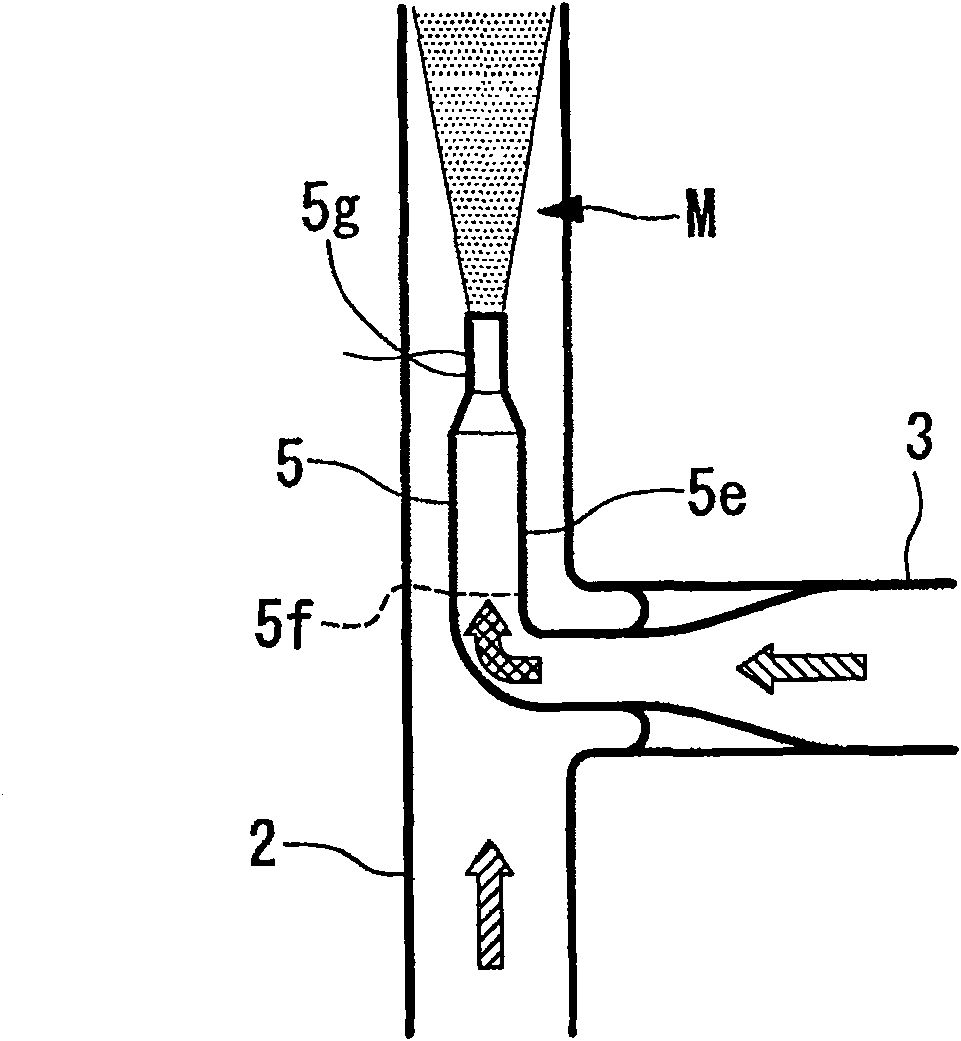
[0098] Next, refer to image 3 A second embodiment of the present invention will be described.
[0099] The difference between this embodiment and the first embodiment is that a diameter-reducing portion 5g is provided at the front end portion 5e of the reducer 5, and the rest is the same as that of the first embodiment. Therefore, descriptions of the same structures are omitted.
[0100] like image 3 As shown, on the downstream end side of the front end portion 5e of the reducer 5, a reduced diameter portion 5g having an inner diameter smaller than that on the upstream side is provided. Therefore, the low-temperature water flowing in the branch pipe 3 and introduced into the reducer 5 is further accelerated at the reduced diameter portion 5g. Therefore, the high-temperature water flowing outside the reducer 5 can be prevented from flowing backward into the reducer 5 . Thereby, since the temperature interface does not reach the inside of the reducer 5, the welding wire 5f...
no. 3 approach
[0104] Next, refer to Figure 5 A third embodiment of the present invention will be described.
[0105] The difference between this embodiment and the first embodiment is that an inner cylinder 10 is provided at the front end of the reducer 5 , and the other aspects are the same. Therefore, descriptions of the same structures are omitted.
[0106] like Figure 5 As shown, the inner cylinder 10 is inserted into the inside of the front end part 5e of the reducer 5. The downstream end 10a of the inner cylinder 10 is arranged on the downstream side of the downstream end 5a of the reducer 5 . A gap having an annular cross section is formed between the outer peripheral wall of the inner cylinder 10 and the inner peripheral wall of the front end portion 5e of the reducer 5 .
[0107] According to this embodiment, since the inner cylinder 10 is provided inside the reducer 5, and a gap is formed between the inner peripheral wall of the reducer 5 and the outer peripheral wall of the...
PUM
 Abstract
Description
Claims
Application Information
 - R&D
- Intellectual Property
- Life Sciences
- Materials
- Tech Scout
- Unparalleled Data Quality
- Higher Quality Content
- 60% Fewer Hallucinations
Browse by: Latest US Patents, China's latest patents, Technical Efficacy Thesaurus, Application Domain, Technology Topic, Popular Technical Reports.
© 2025 PatSnap. All rights reserved.Legal|Privacy policy|Modern Slavery Act Transparency Statement|Sitemap|About US| Contact US: help@patsnap.com