
Wireless network communication apparatus

A communication device and a wireless network technology, applied in the field of mobile communication, can solve the problems that cannot meet the requirements of the EUTRAN system, cannot guarantee the sequential reception of the PDCP layer, and achieve the effects of saving overhead, reducing complexity, and improving data transmission efficiency

Inactive Publication Date: 2009-12-16
HUAWEI TECH CO LTD
View PDF5 Cites 0 Cited by
  • Summary
  • Abstract
  • Description
  • Claims
  • Application Information

AI Technical Summary

Problems solved by technology

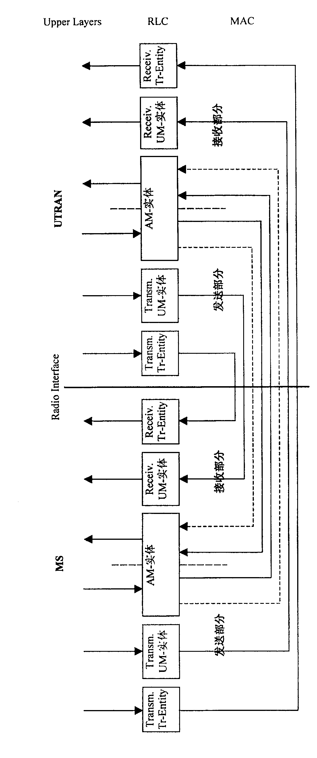
[0033] To sum up, the shortcomings of the existing technology are: the RLC layer in R6 is located in the radio network control (RNC), the sending end of the RLC UM entity and AM entity supports split concatenation based on equal-sized PDUs, and the receiving end supports SDU orderly Submission and out-of-order delivery, and the UM and AM entities of RLC are established according to the business
In the EUTRAN system, the RNC is canceled, and the RLC layer is moved down to the base station. It can be used as a separate layer, or it can be combined with the MAC layer to form the MAC+ layer. In this way, in order to better utilize the transmission efficiency of the air interface and reduce filling, split cascading can Based on the flexible PDU size; and the access network architecture of the EUTRAN system is an all-IP architecture, and the PDCP layer is located at the access gateway (aGW). In this way, only by receiving data in the order in which the data packets are sent by the PDCP layer can the errors in decompression be reduced. However, the orderly delivery of SDUs at the RLC layer cannot guarantee the orderly reception of the PDCP layer.
In summary, the RLC layer AM and UM entity characteristics of the R6 protocol can no longer meet the requirements of the EUTRAN system

Method used


Image

  • Wireless network communication apparatus
  • Wireless network communication apparatus
  • Wireless network communication apparatus

Examples


Embodiment 1

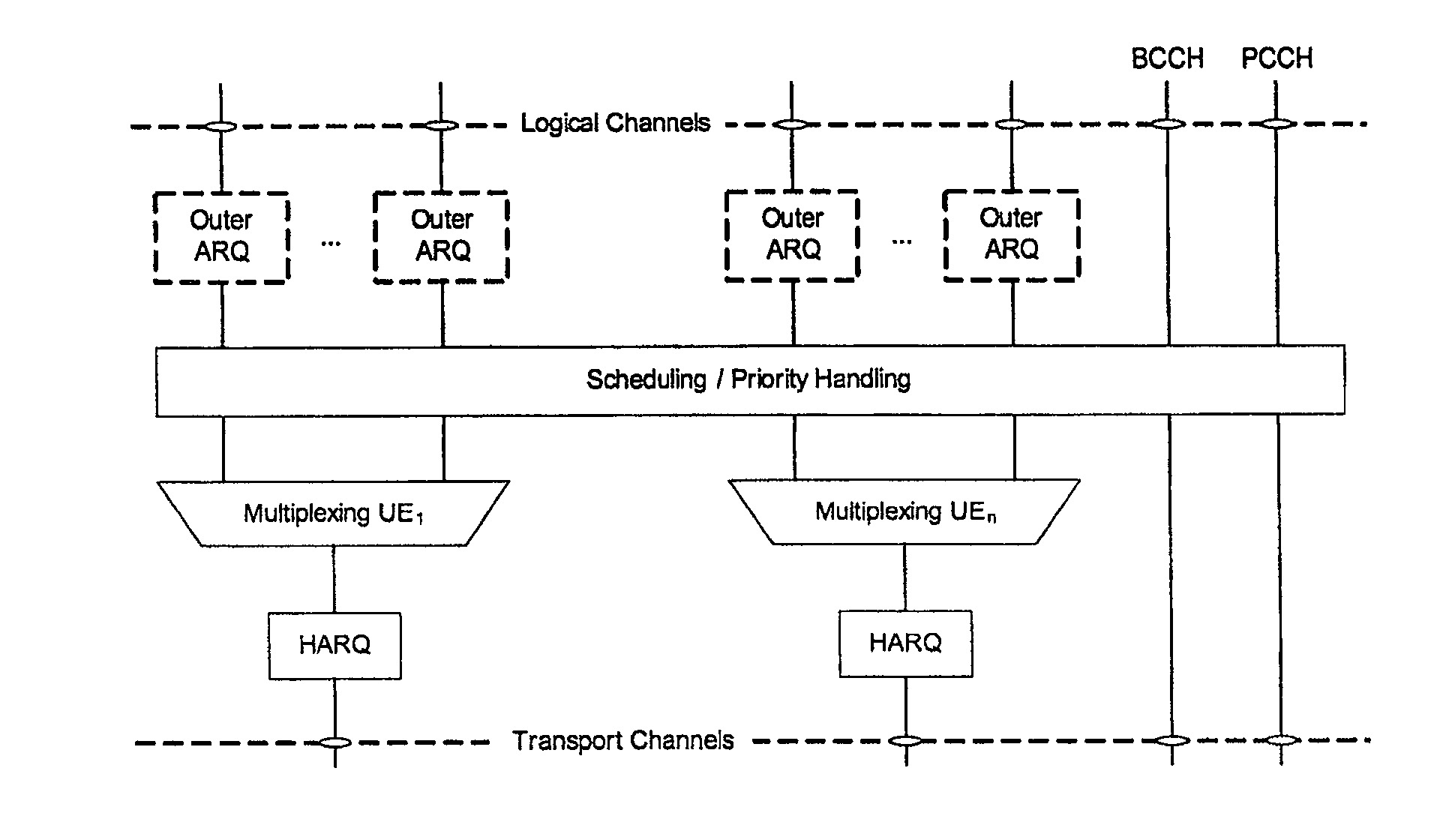
[0074] exist Image 6 , shows the AM mode physical architecture of the outer ARQ of the base station of the present invention, wherein the service data unit is transmitted to the outer ARQ module of the MAC+ layer through the logical channel, and the MAC+ layer communicates with the physical layer through the transmission channel.

[0075] The sending part of the AM mode entity includes: a transmission buffer unit, which transmits and buffers the high-level service data units transmitted through the logical channel 1; a split cascading unit, which splits and concatenates the service data units after the transmission buffer, and generates a protocol The data unit; the retransmission buffer unit, retransmits and buffers the protocol data unit after split and concatenated, and divides and connects the protocol data unit after retransmission buffer again; the outer ARQ sends the protocol data unit after split and concatenated to The MAC in the base station, the MAC in the base sta...

Embodiment 2

[0089] exist Figure 8 , shows the AM mode entity architecture of the ERLC of the base station of the present invention, wherein the service data unit of the upper layer is transmitted to the ERLC, and the ERLC transmits the protocol data unit to the EMAC through a logical channel, and the EMAC communicates with the physical layer through a transport channel.

[0090] The sending part of the AM mode entity includes: the transmission cache unit transmits and caches the high-level service data unit (service 1); the division and concatenation unit divides and concatenates the service data units after the transmission cache to generate a protocol data unit; retransmission The cache unit retransmits and caches the protocol data units after splitting and cascading, and splits and connects the protocol data units after retransmission caching again; ERLC transmits the protocol data units after splitting and cascading to EMAC through logical channel 1, and EMAC Scheduling the divided a...

Embodiment 3

[0105] exist Figure 10 , shows the AM mode entity architecture of the outer ARQ of the user equipment (UE) in the present invention, wherein the service data unit is transmitted to the outer ARQ module of the MAC+ layer through the logical channel, and the MAC+ layer communicates with the physical layer through the transport channel.

[0106] The sending part of the AM mode entity includes: a transmission buffer unit, which transmits and buffers the high-level service data units transmitted through the logical channel 1; a split cascading unit, which splits and concatenates the service data units after the transmission buffer, and generates a protocol The data unit; the retransmission buffer unit, retransmits and buffers the protocol data unit after split and concatenated, and divides and connects the protocol data unit after retransmission buffer again; the outer ARQ sends the protocol data unit after split and concatenated to The MAC in the base station and the MAC in the U...


PUM


Abstract

The present invention provides a wireless network communication device, including at least one upper-layer automatic request for retransmission entity, wherein the automatic request for retransmission entity in acknowledgment mode has a sending part and a receiving part: the sending part includes: a split cascading unit for The data unit is divided and cascaded; the retransmission buffer unit is used to cache the divided and concatenated protocol data unit, and the cached protocol data unit is processed; the receiving part includes: a rearrangement unit for receiving The protocol data units are sorted; the reorganization unit reorganizes the sorted protocol data units, and submits them to the high-level after forming service data units; wherein, the splitting and cascading of the data units includes: inputting the splitting and cascading units The retransmitted PDUs are divided and concatenated again, and corresponding data header information is added. It is used for the new outer ARQ entity architecture proposed for the EUTRAN system, providing functions that cannot be supported by the R6 protocol architecture, and improving system performance.

Description

technical field [0001] The present invention relates to the technical field of mobile communication, in particular to the optimization of the physical architecture of the radio link layer (RLC) in the acknowledged mode (AM) and the unacknowledged mode (UM) in the base station of the evolved universal terrestrial radio access network, specifically A wireless network communication device. Background technique [0002] From the perspective of the evolution of the wideband CDMA (WCMDA) system, in the early 1990s, some communication companies and research organizations in Europe started research on WCDMA. From 1998 to now, the technical specifications of the WCDMA system have gone through Specification (Release) 99, Release 4, Release 5, and Release 6 are several stages, and the standardization work on Release 7 has already begun to be implemented. At the same time, the longer-term LTE (Long Term Evolution) research has gradually become a new focus of standardization work. [0...

Claims


Application Information

Patent Timeline
Patent Type & Authority Patents(China)
IPC IPC(8): H04L1/18
Inventor 邵飞
Owner HUAWEI TECH CO LTD
Learn More