
Circuit for improving high-pressure line scanning output power of TV set

A technology of output power and line scanning, which is applied in the field of image processing, can solve the problem of difficult adjustment of line scanning linear compensation circuit

Inactive Publication Date: 2009-12-02
KONKA GROUP
View PDF3 Cites 0 Cited by
  • Summary
  • Abstract
  • Description
  • Claims
  • Application Information

AI Technical Summary

Problems solved by technology

[0028] The purpose of the present invention is to provide a circuit for improving the output power of high-voltage horizontal scanning of cathode ray tube TV sets, so as to solve the problems encountered in existing ultra-thin, high-definition, progressive scanning TV sets equipped with small inductance deflection coil picture tubes and solutions Difficulty in adjusting line scan linear compensation circuit

Method used


Image

  • Circuit for improving high-pressure line scanning output power of TV set
  • Circuit for improving high-pressure line scanning output power of TV set
  • Circuit for improving high-pressure line scanning output power of TV set

Examples


Embodiment Construction

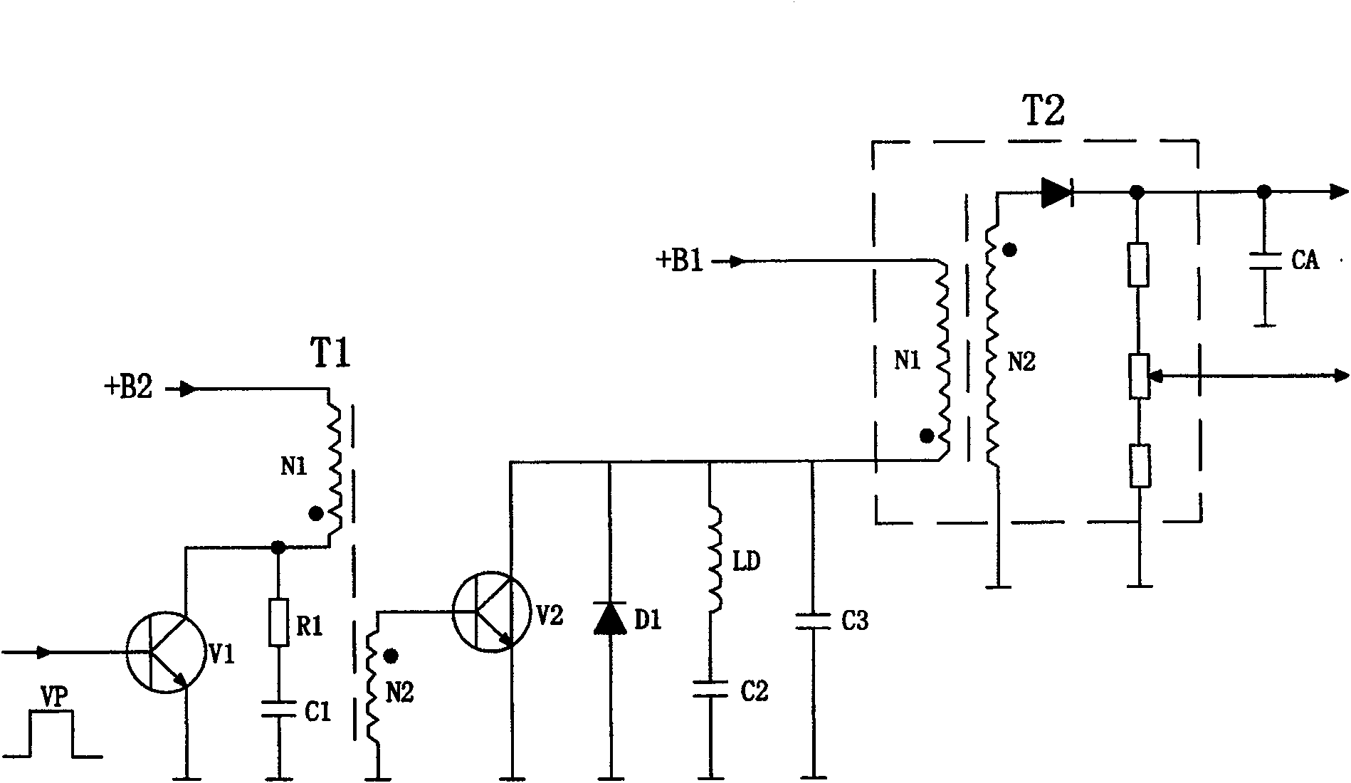
[0040] The high-voltage line scanning circuit of the TV set of the present invention, such as Figure 4 As shown, it includes a line scan drive signal amplifier 1, a line drive transformer 2, a line scan power amplifier 3 and a line flyback transformer 4, and the line scan drive signal amplifier 1 is connected in parallel with an RC damping circuit 5, and its collector is connected to the line drive transformer. The primary coil 21 is connected, and the two secondary coils 22, 23 of the row drive transformer are connected with the bases of the row scanning power amplifiers 31, 32 respectively, and the row scanning power amplifier 3 is connected in parallel with the damping diode 5 and the row reverse resonance 8 respectively. After the scanning deflection coil 6 and the S correction capacitor 7 are connected in series, they are connected in parallel with the horizontal scanning power amplifier 3, and the collector of the horizontal scanning power amplifier 31 is connected with ...


PUM


Abstract

The invention discloses a circuit for increasing the output power of high-voltage horizontal scanning of a cathode ray tube television set. The circuit comprises a horizontal scanning drive signal amplifier, a horizontal driving transformer, a horizontal scanning power amplifier and a horizontal flyback transformer. The horizontal scanning driving signal amplifier is connected in parallel with a RC damping circuit, its collector is connected to the primary coil of the horizontal drive transformer, the two secondary coils of the horizontal drive transformer are respectively connected to the two bases of the horizontal scanning power amplifier, and the horizontal scanning power amplifier is respectively connected to the damping diode and the horizontal reverse stroke The resonant capacitor is connected in parallel, and the horizontal scanning deflection coil and the S correction capacitor are connected in parallel with the horizontal scanning power amplifier after being connected in series, and a collector of the horizontal scanning power amplifier is connected with the primary coil of the horizontal flyback transformer, and the horizontal flyback transformer is composed of initial, The secondary coil is composed of a CR circuit, and the horizontal scanning power amplifier is composed of two high-voltage transistors or field effect transistors connected in series, so that the output power of horizontal scanning can be increased by increasing the working voltage of the horizontal scanning input power.

Description

technical field [0001] The invention relates to an image processing technology of a cathode ray tube (CRT) television, in particular to a circuit for increasing the output power of high-voltage horizontal scanning of the cathode ray tube television. Background technique [0002] CRT TVs appearing on the market are gradually developing towards ultra-thin, large-screen, progressive scanning, high-definition, etc. Therefore, the technical performance of the scanning circuit is also improved accordingly. [0003] For ultra-thin TV sets, due to the shortening of the picture tube, the corresponding scanning deflection angle needs to be increased, so that the line and field scanning deflection power also needs to be increased; [0004] For progressive scan or high-definition televisions, due to the increase in the number of line scan lines, the line scan frequency needs to be increased, and the corresponding line scan deflection power should also be increased. [0005] In order to...

Claims


Application Information

Patent Timeline
Patent Type & Authority Patents(China)
IPC IPC(8): H04N3/16H04N3/23
Inventor 陶显芳
Owner KONKA GROUP
Learn More