
Apparatus and method for controlling the state variable of an integrator stage in a modulator

a technology of integrator stage and integrator stage, which is applied in the field of apparatus and method for controlling the state variable of an integrator stage in a modulator, can solve the problems of large transients in the output signal, waste of capacity and the area of the lossy circuit, and large utilization of chip spa

Active Publication Date: 2006-05-30
ANALOG DEVICES INC
View PDF11 Cites 49 Cited by
  • Summary
  • Abstract
  • Description
  • Claims
  • Application Information

AI Technical Summary

Benefits of technology

[0007]It is a further object of this invention to provide such an apparatus and method which dynamically increases the lossiness of an integrator stage in a modulator during an overdrive condition without the need to add additional capacitance.
[0008]It is a further object of this invention to provide such an apparatus which eliminates the need for a reset switch between the added capacitance and the integrating capacitor of the integrator stage.
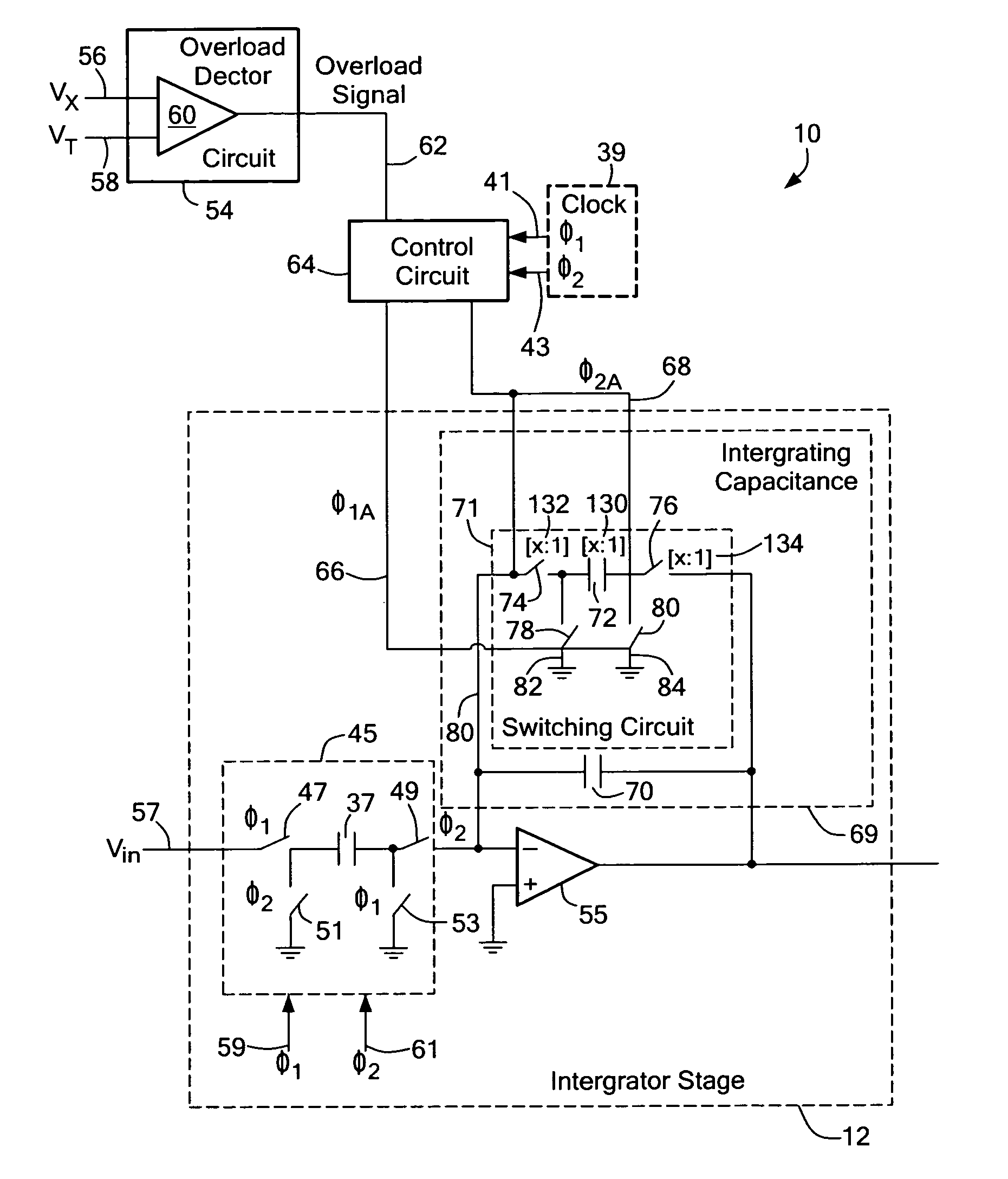
[0009]This invention results from the realization that an improved apparatus and method for controlling the state variables(s) of an integrator stage in a modulator can be achieved, not by adding capacitance to an integrator stage in a modulator with a reset switch to increase the lossiness of the integrator stage when the modulator is overdriven, but instead by enabling, during an overdriven condition, one portion of the integrating capacitance itself to repeatedly receive charge from another portion of the integrating capacitance and then repeatedly drain that charge to a discharge path to dynamically increase the lossiness of the integrator stage and control the state variable(s) in the modulator.
[0011]This invention features an apparatus for controlling the state variable of an integrator stage in a modulator including a detector circuit for generating an overload signal when the modulator is overdriven, a control circuit responsive to the overload signal for generating switching control signals during the overdriven condition, and an integrating capacitance circuit having an unswitched portion and a switched portion and responsive to the switching control signals for repeatedly connecting the switched portion between the unswitched portion and a discharge path to receive and drain charge when the modulator is overdriven to increase the lossiness of the integrator and control a state variable of the integrator stage in the modulator.
[0014]This invention also features a method for controlling the state variable of an integrator stage in a modulator including the steps of detecting when the modulator is overdriven, generating switching control signals during the overdriven condition, and actuating an integrating capacitance circuit with the switching control signals during the overdriven condition to repeatedly disconnect a switched portion from an unswitched portion of the integrating capacitance circuit during one phase to dump charge and connect the switched portion to an unswitched portion during an alternate phase to drain charge from the unswitched portion to increase the lossiness of the integrator stage and control a state variable of the integrator stage in the modulator.

Problems solved by technology

However, resetting the state variable(s) of the integrator stage to zero results in large transients in the output signal.
However, the apparatus as disclosed in the '009 patent utilizes significant chip space because two separate capacitors must be utilized: one for the integrating capacitor and another for the “lossy circuit”.
When the modulator is not overdriven, the capacity of and the area utilized by the lossy circuit is wasted.

Method used


Image

  • Apparatus and method for controlling the state variable of an integrator stage in a modulator
  • Apparatus and method for controlling the state variable of an integrator stage in a modulator
  • Apparatus and method for controlling the state variable of an integrator stage in a modulator

Examples


Embodiment Construction

[0022]Aside from the preferred embodiment or embodiments disclosed below, this invention is capable of other embodiments and of being practiced or being carried out in various ways. Thus, it is to be understood that the invention is not limited in its application to the details of construction and the arrangements of components set forth in the following description or illustrated in the drawings. If only one embodiment is described herein, the claims hereof are not to be limited to that embodiment. Moreover, the claims hereof are not to be read restrictively unless there is clear and convincing evidence manifesting a certain exclusion, restriction, or disclaimer.

[0023]Conventional modulator 10, FIG. 1, is a typical higher-order modulator. In this example, modulator 10 is a third order delta-sigma modulator and includes three integrator stages 12, 14, and 16. The output of integrator stage 12 is the input to integrator stage 14 and the output of integrator stage 14 is the input to i...


PUM


Abstract

An apparatus for controlling the state variable of an integrator stage in a modulator including a detector circuit for generating an overload signal when the modulator is overdriven, a control circuit responsive to the overload signal for generating switching control signals during the overdriven condition, and an integrating capacitance circuit having an unswitched portion and a switched portion and responsive to the switching signals for repeatedly connecting the switched portion between the unswitched portion and a discharge path to receive and drain charge when the modulator is overdriven to increase the lossiness of the integrator stage and control a state variable of the modulator.

Description

FIELD OF THE INVENTION[0001]This invention relates to an apparatus and method for dynamically increasing the lossiness of an integrating capacitance of an integrator stage in a modulator during an overdrive condition to effectively control the state variable(s) of the integrator stage.BACKGROUND OF THE INVENTION[0002]Higher-order modulators, e.g., third-order or higher modulators, such as sigma-delta modulators, pulse-width modulators, and the like require some mechanism to reset or control the modulator when the modulator is overdriven to prevent unstable conditions that can produce undesirable transients in the output signal.[0003]One conventional device to control a higher-order modulator from being overdriven relies on resetting the state variable(s) (e.g., any quantity that indicates the current state of the modulator, such as the output voltage at each integrator stage, or the charge on the integrating or switched capacitor) to zero, or a stable point, when the modulator enter...

Claims


Application Information

Patent Timeline
Patent Type & Authority Patents(United States)
IPC IPC(8): H03M3/00
CPCH03M3/36H03M3/438H03M3/422
Inventor GAALAAS, ERIC
Owner ANALOG DEVICES INC
Learn More