
Bearing unit for railway carriages

A technology for bearing devices and railway vehicles, which is applied in the direction of railway vehicles, bearings, roller bearings, etc., can solve the problems of difficulty in manufacturing and assembling bearing devices, increasing the number of components, and deterioration of lubricants, etc., and achieves easy maintenance and management, manufacturing and assembling Ease, the effect that assemblability improves

Inactive Publication Date: 2009-10-21
NTN CORP
View PDF9 Cites 0 Cited by
  • Summary
  • Abstract
  • Description
  • Claims
  • Application Information

AI Technical Summary

Problems solved by technology

[0009] Image 6 The bearing device for railway vehicles is effective in suppressing the wear of the inner wheel 3 and the rear cover 11 by the partition plate 32 and reducing the generation of fretting wear powder. However, if the generated trace amount of wear powder accumulates, it will flow out to the bearing. Internally, problems such as deterioration of the lubricant inside the bearing occur, and it is difficult to suppress the occurrence of this problem
[0010] exist Figure 7 In the bearing device, although the elastic member 33 can suppress the fretting wear powder from the contact part X of the inner wheel 3 and the rear cover 11 to the bearing, the defects caused by the generation of wear powder and the accumulation of the wear powder at the contact part X still exist.
[0011] From the above, it can be considered that the Image 6 the clapboard with Figure 7 In this case, the number of components increases, the number of assembly man-hours for the entire bearing device increases, and the manufacturing and assembly of the bearing device becomes more difficult.

Method used


Image

  • Bearing unit for railway carriages
  • Bearing unit for railway carriages
  • Bearing unit for railway carriages

Examples


Embodiment Construction

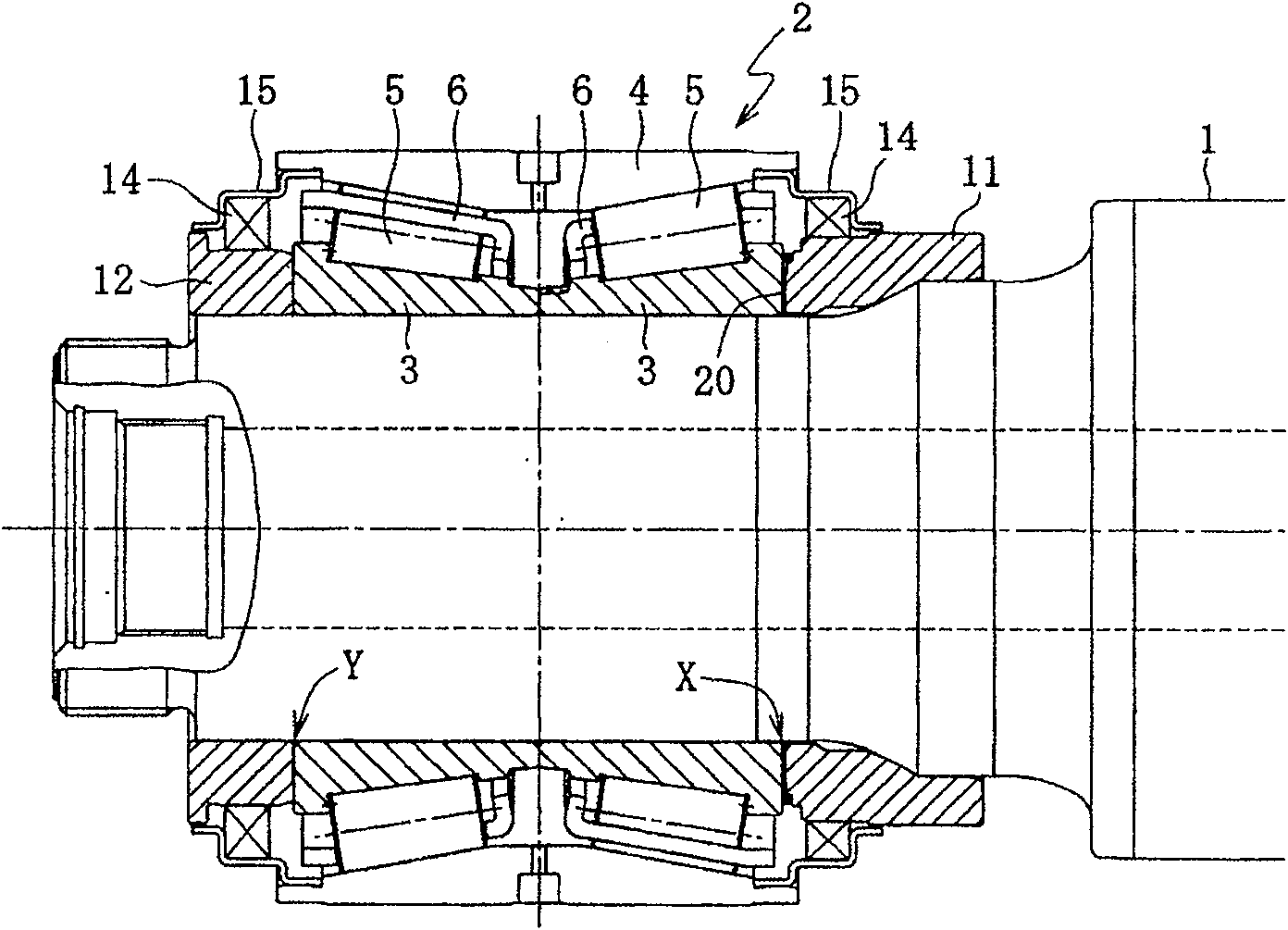
[0052] Hereinafter, the first embodiment will be described in order with reference to FIGS. 1 to 3. The basic structure of the bearing device for railway vehicles of this embodiment and Figure 5 The bearing device is the same, so for the Figure 5 The same or equivalent parts are marked with the same symbols to avoid repetitive explanations.

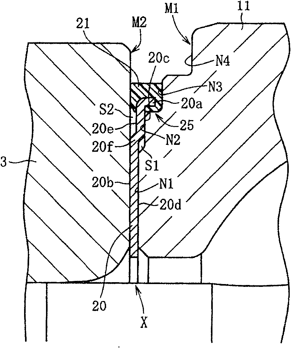
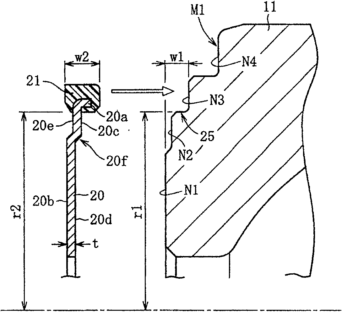
[0053] In the first embodiment shown in FIGS. 1(A) and (B), a ring-shaped partition plate 20 with an elastic seal is sandwiched in the contact portion X between the inner wheel 3 and the rear cover 11 (circular member) , Both sides of the ring-shaped partition 20 abut the rear width of the inner wheel 3 and the front width of the rear cover 11. The ring-shaped partition 20 with elastic seal is an integral member in which an elastic seal 21 such as an annular rubber ring is integrally fixed to the outer peripheral edge of the partition 20 of a circular ring-shaped brass thin plate.

[0054] The ring-shaped partition 20 is made of a press-for...


PUM


Abstract

Emergence of fretting worn powder is to be suppressed, and intrusion of the worn powder that has emerged into an internal area of the bearing. A ring spacer (20) is interposed between an end face (M2) of an inner race (3) of the bearing (2) to be mounted on a wheel axle, and an end face (N2) of a rear cover (11) (ring member) to be mounted on the wheel axle (1) for axial positioning of the inner race (3) with respect to the wheel axle (1). An elastic seal ring (21) is integrally fixed to an outer periphery of the ring spacer (20). The elastic seal ring (21) is elastically fitted to an outer circumference of a recessed stepped portion (25) formed on the end face of the rear cover (11). The elastic seal ring (21) is thus pressed against the opposing end faces of the inner race (3) and the rear cover (11). Inside the elastic seal ring (21), a storage space for the worn powder is provided.

Description

Technical field [0001] The present invention relates to a bearing device that uses rolling bearings to support the axles of railway vehicles. Background technique [0002] The axle bearing device of a railway vehicle includes a rolling bearing mounted on the axle, and a set of ring members before and after the roller bearing is mounted on the axle to perform axial positioning of the inner wheel of the rolling bearing. The ring parts are the back cover abutting on the rear width of the inner wheel and the oil interception ring abutting on the front width, or the back cover and the front cover abutting on the front and rear sides of the inner wheel, and are made of heat-treated carbon Steel composition. [0003] Figure 5 Shows a general bearing device for railway vehicles. In the bearing device, a set of ring members of the rear cover 11 and the oil interceptor 12 abut against the two ends of the inner wheel 3 of the rolling bearing 2 mounted on the axle 1. The rolling bearing 2 ...

Claims


Application Information

Patent Timeline
Patent Type & Authority Patents(China)
IPC IPC(8): B61F15/22F16C35/12F16C19/38F16C33/58F16C33/76F16C33/78
CPCB61F15/22F16C33/768F16C19/386F16C2326/10F16C33/7813F16C35/063
Inventor 三木大辅石川司郎
Owner NTN CORP
Learn More