
Circular lighting device and its manufacturing method

A technology for lighting devices and manufacturing methods, applied in lighting devices, components of lighting devices, cooling/heating devices for lighting devices, etc., can solve the problem of poor electrical contact between LED wires and printed wiring boards, and the inability to easily manufacture rings Shaped lighting devices, high installation density and other issues, to achieve the effect of preventing poor electrical contact

Inactive Publication Date: 2009-08-26
KYOTO DENKIKI KK
View PDF6 Cites 2 Cited by
  • Summary
  • Abstract
  • Description
  • Claims
  • Application Information

AI Technical Summary

Problems solved by technology

Since the actual mounting density of many LEDs with respect to the printed wiring board is relatively high, it is not easy to bend the printed wiring board into a truncated conical shape, so there is a problem that ring lighting devices cannot be easily manufactured
In addition, if the printed wiring board is bent into a truncated cone shape as described above, stress acts on the printed wiring board, and thus the stress acts on the lead wires of the LEDs soldered on the printed wiring board. The problem: Cracks occur in the soldering part of the LED wire, which may cause poor electrical contact between the LED wire and the printed wiring board

Method used


Image

  • Circular lighting device and its manufacturing method
  • Circular lighting device and its manufacturing method
  • Circular lighting device and its manufacturing method

Examples


Embodiment Construction

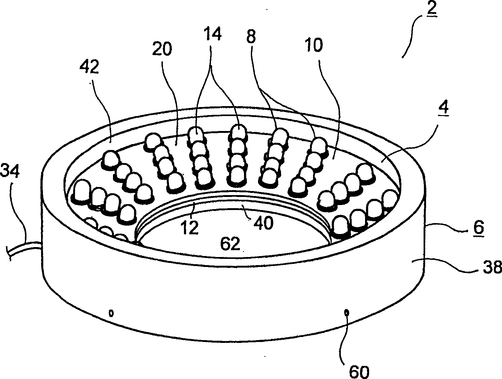
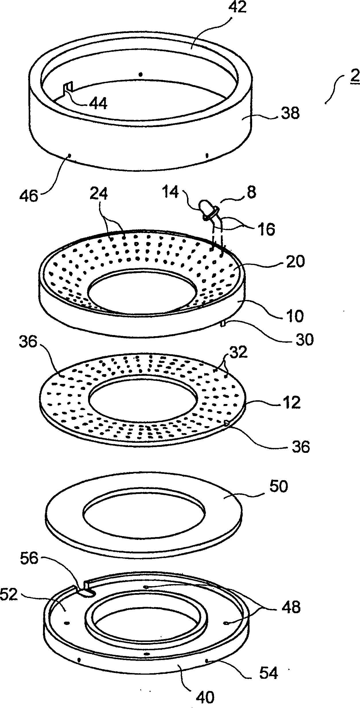
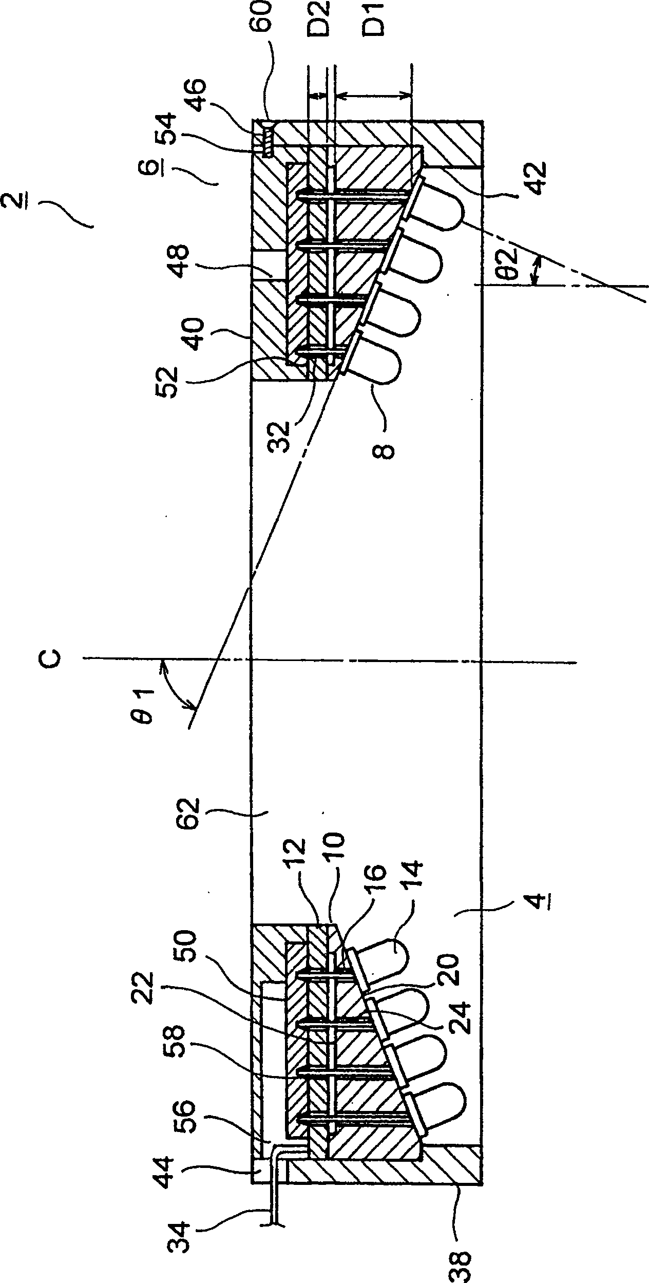
[0030]Hereinafter, various embodiments of the ring lighting device and its manufacturing method according to the present invention will be described with reference to the drawings. figure 1 is a perspective view showing the ring lighting device according to the first embodiment of the present invention, figure 2 yes means figure 1 An exploded perspective view of the ring lighting device, image 3 yes figure 1 A schematic cross-sectional view of the ring lighting device, Figure 4 yes means image 3 An enlarged cross-sectional view of the through-hole of the platen and its surrounding structure.

[0031] exist Figure 1 to Figure 4 In the figure, the illustrated ring lighting device 2 includes a ring light source 4 that irradiates light in a ring shape, and a housing 6 for holding the ring light source 4 . Hereinafter, each of these constituent elements will be described in detail.

[0032] The annular light source 4 includes a plurality of LEDs 8 , an annular base 10 s...


PUM


Abstract

A ring type illuminator and a manufacturing method thereof are provided to stably maintain electrical connection between a lead of an LED(Light Emitting Diode) and a printed wiring board by firmly soldering the lead of the LED on both sides of the printed wiring board. A ring type illuminator includes a plurality of LEDs(8) and a printed wiring board(12). The printed wiring board is plate type or ring type. A ring type support plate(10) is interposed between light emitting units(14) of the LEDs and has a plurality of through holes(24) and an inclined surface(20) inclined downward to the inside of a diameter direction. Leads(16) of the LEDs are soldered by passing through a plurality of through holes(32) of the printed wiring board. The light emitting units of the LEDs are vertically supported on the inclined surface of the support plate.

Description

technical field [0001] The present invention relates to a ring lighting device for illuminating an object to be inspected, for example, in image processing inspection and the like, and a method for manufacturing the same. Background technique [0002] Conventionally, it has been used when inspecting the quality of industrial products such as printed wiring boards and semiconductors on the manufacturing line, such as poor soldering or adhesion of foreign matter, or printing errors such as the date of manufacture printed on beverage cans. Image processing inspection based on imaging by CCD camera etc. In this image processing inspection, a ring illumination device for illuminating an inspection object arranged in an illumination area is used. [0003] The ring lighting device includes a ring light source that irradiates light in a ring shape, and the ring light source includes a plurality of LEDs and a flexible printed wiring board electrically connected to the plurality of L...

Claims


Application Information

Patent Timeline
Patent Type & Authority Patents(China)
IPC IPC(8): F21S2/00F21V23/00F21V19/00H05K1/18F21V29/00F21Y103/02F21Y101/02G03B15/02G03B15/05H01L33/00
Inventor 矢岛诚藤井崇弘
Owner KYOTO DENKIKI KK
Learn More