
Drive system for chain sprockets of chain drives

A technology of driving device and chain transmission, which is applied in the direction of transmission device, transmission device control, gear transmission device, etc.

Inactive Publication Date: 2009-08-12
CATERPILLER GLOBAL MINING EURO GMBH
View PDF13 Cites 0 Cited by
  • Summary
  • Abstract
  • Description
  • Claims
  • Application Information

AI Technical Summary

Problems solved by technology

In addition, there are significant difficulties with the use of variable frequency motors on chain drives, namely, to achieve the desired starting effect for chain conveyors for starting loads or for pulling plows inserted into the working face

Method used

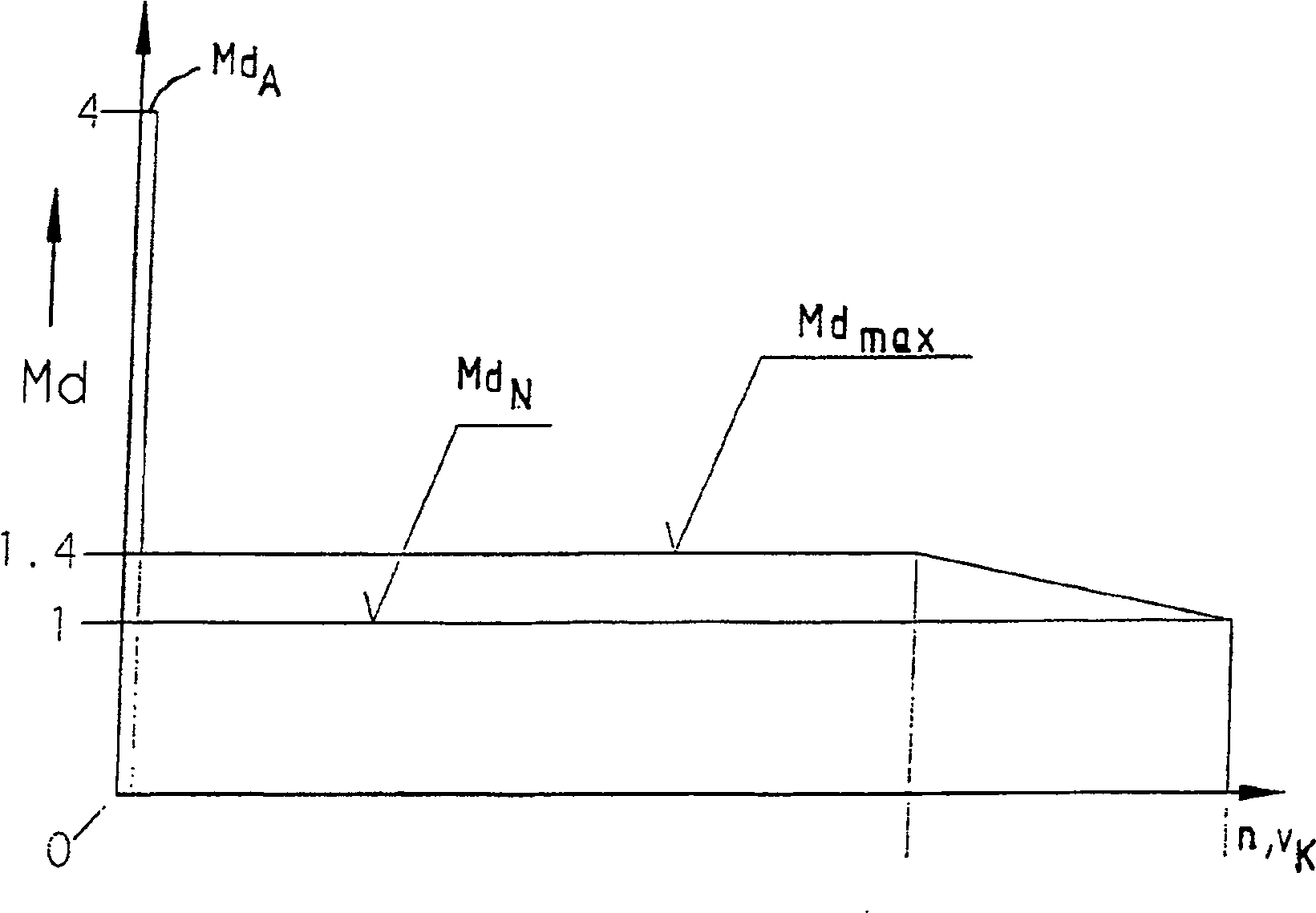

Image

  • Drive system for chain sprockets of chain drives
  • Drive system for chain sprockets of chain drives
  • Drive system for chain sprockets of chain drives

Examples


Embodiment Construction

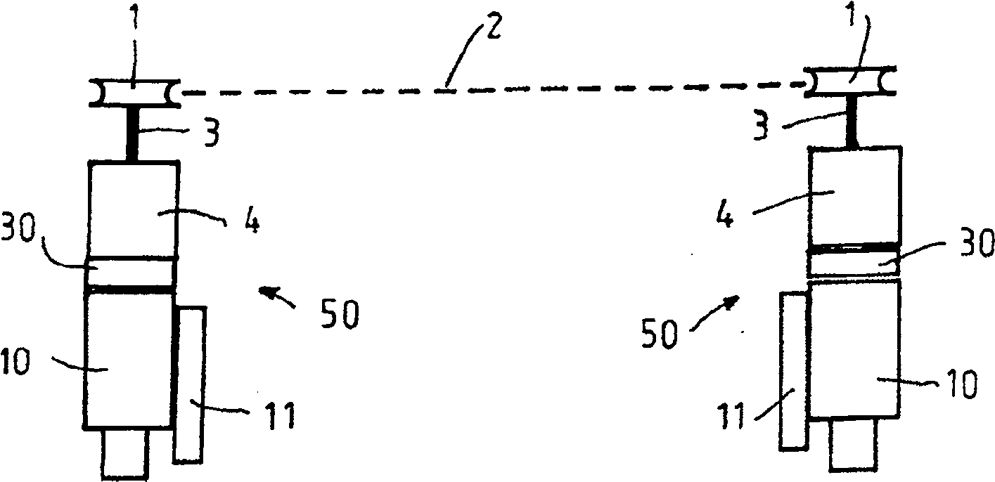
[0020] figure 1Two chain drives, indicated generally at 50, are shown for driving a continuous chain 2 which runs around two sprockets 1 of the chain drive 50, on a working face or roadway formed as a chain scraper conveyor In the case of a conveyor the chain consists of its scraper conveyor, while in the case of a plow it is a plow chain which moves the plow (not shown) along the working face. The sprocket 1 is responsible for the deflection of the chain 2 and is driven in each case by a drive unit, to which the sprocket is connected in a rotationally fixed manner via a sprocket shaft 3 . The drive unit of the two chain drives 50 consists of an electric AC asynchronous motor consisting of a variable frequency motor 10 with a combined switch box 11 for the frequency converter line, which is connected in the middle with the condition of a cantilever transmission 30 The lower is coupled with the overload protection and load balancing reducer 4. The overload protection and load...


PUM


Abstract

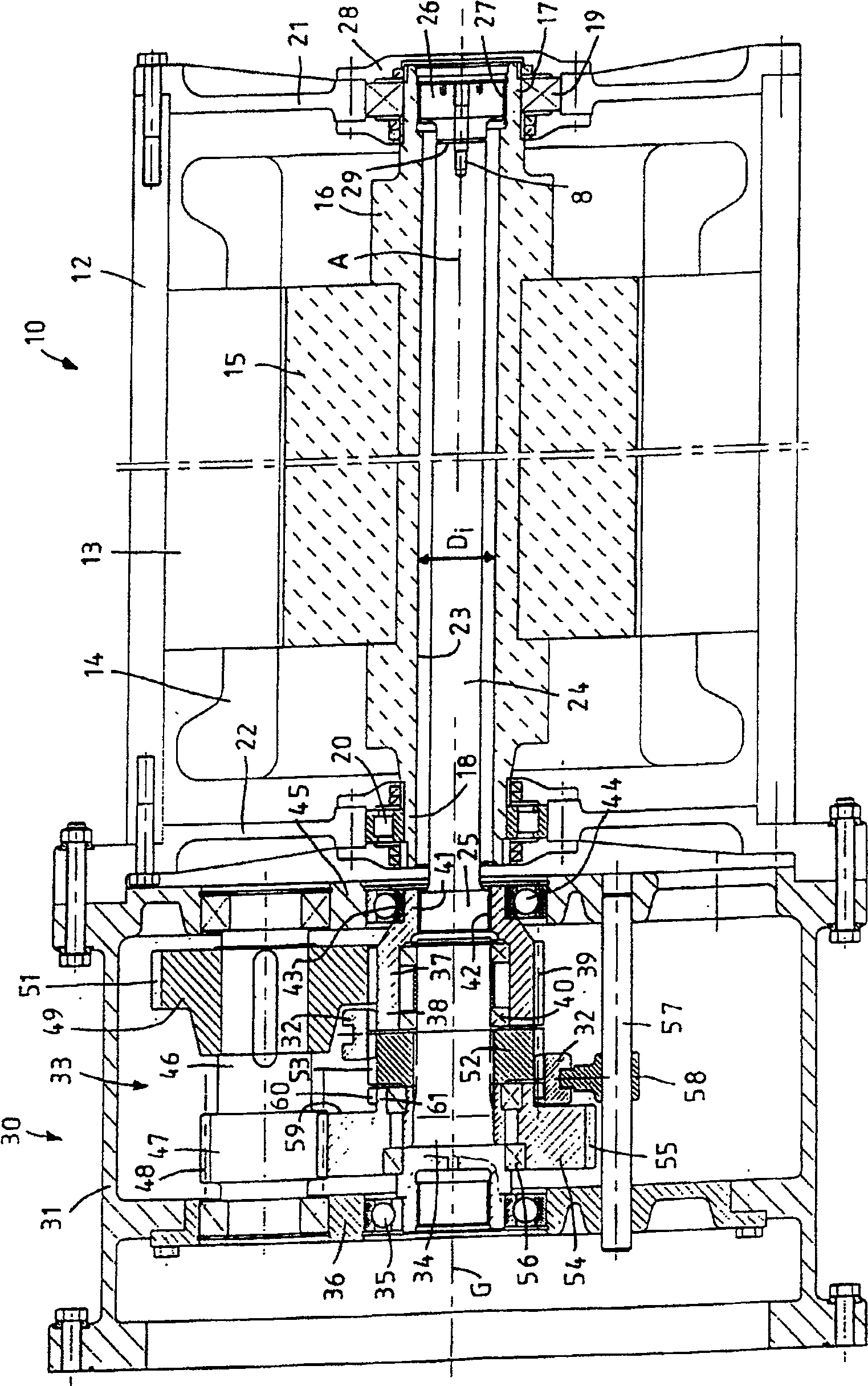
The invention relates to a drive device for a sprocket (1) of a chain drive, in particular for driving a chain scraper conveyor or a chain traction plow for underground mining, having an asynchronous motor and a A transmission mechanism composed of a reducer (4), wherein the reducer (4) is composed of an overload reducer and has a controllable plate clutch in order to balance the overload, through which the force flow between the asynchronous motor and the sprocket can be separated . According to the provisions of the present invention, the asynchronous motor is composed of a variable frequency motor (10), and a cantilever transmission (30) is intermediately connected in the transmission mechanism between the overload reducer (4) and the motor shaft of the variable frequency motor. The cantilever transmission (30) is designed as a two-stage gear transmission (33) with a starting changeover stage and a normal changeover stage, by means of which the two-stage gearbox is used on chain scraper conveyors for starting loading or for free hauling. The required starting effect is achieved in the starting transition stage of the plow. The two-stage gear transmission has a drive-side sun gear (37) rotatably supported on the reducer shaft (34) and an output-side sun gear (54) rotatably supported on the reducer shaft. An intermediate wheel (52) that is anti-rotationally connected to the reducer shaft (34) is disposed between the driving side sun gear (37) and the output side sun gear (54), wherein the intermediate wheel (52) passes through A shifting device (32, 57, 58) can be selectively coupled in a rotationally fixed manner to a drive-side or output-side sun gear (37, 54).

Description

technical field [0001] The invention relates to a driving device for a sprocket of a chain drive, especially for driving a chain scraper conveyor or a chain-type traction plow for underground mining, which has an asynchronous motor and a reducer Constructed transmission mechanism, wherein the reducer is composed of overload and load balancing reducer and has a controllable plate clutch for overload balance, through which the force flow between the asynchronous motor and the sprocket can be separated. Background technique [0002] Such drives are known, for example, from DE 40 24 830 A1 or DE 43 16 798 C2. For known drives, unregulated AC asynchronous motors are used. Through the overload and load balancing reducer connected after the drive device is running, the load is balanced between the main drive and the auxiliary drive of the plow or chain scraper conveyor by controlling the plate clutch, so that the plow or chain Optimize the operation of the scraper conveyor and av...

Claims


Application Information

Patent Timeline
IPC IPC(8): F16H59/04F16H3/089B65G23/30E21C29/16H02P27/04F16H3/091
CPCY10T74/19684E21C29/16F16H3/0915F16H2200/0034Y10T74/19307
Inventor 维尔纳·朗根贝格格哈德·默滕维尔纳·博勒
Owner CATERPILLER GLOBAL MINING EURO GMBH
Learn More