
Condensing unit, pressure roller unit and drawing unit

A technology of compressor unit and compacting roller, which is applied in drafting equipment, spinning machine, textile and papermaking, etc., can solve the problem of positioning limitation of the drafting system of the compressor unit, and achieve the effect of stable implementation and stable spinning.

Active Publication Date: 2020-05-05
MASCHINENFABRIK RIETER AG
View PDF20 Cites 0 Cited by
  • Summary
  • Abstract
  • Description
  • Claims
  • Application Information

AI Technical Summary

Problems solved by technology

The positioning of the compressor unit relative to the drafting system is restricted due to the two joints, especially the one arranged in front of the first top roller

Method used


Image

  • Condensing unit, pressure roller unit and drawing unit
  • Condensing unit, pressure roller unit and drawing unit
  • Condensing unit, pressure roller unit and drawing unit

Examples


Embodiment Construction

[0032] In the following description of the illustrated alternative embodiments, identical and / or at least equivalent features with regard to the design and / or mode of action of these embodiments are provided with the same reference numerals. If these features are not specifically explained again, their design and / or mode of operation correspond to those of the features already described.

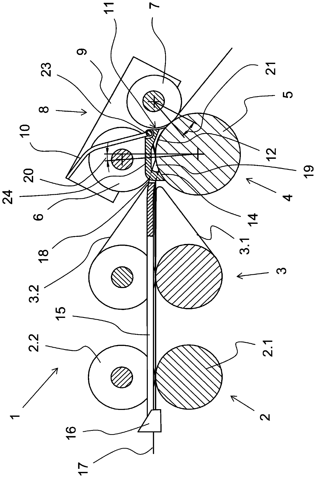
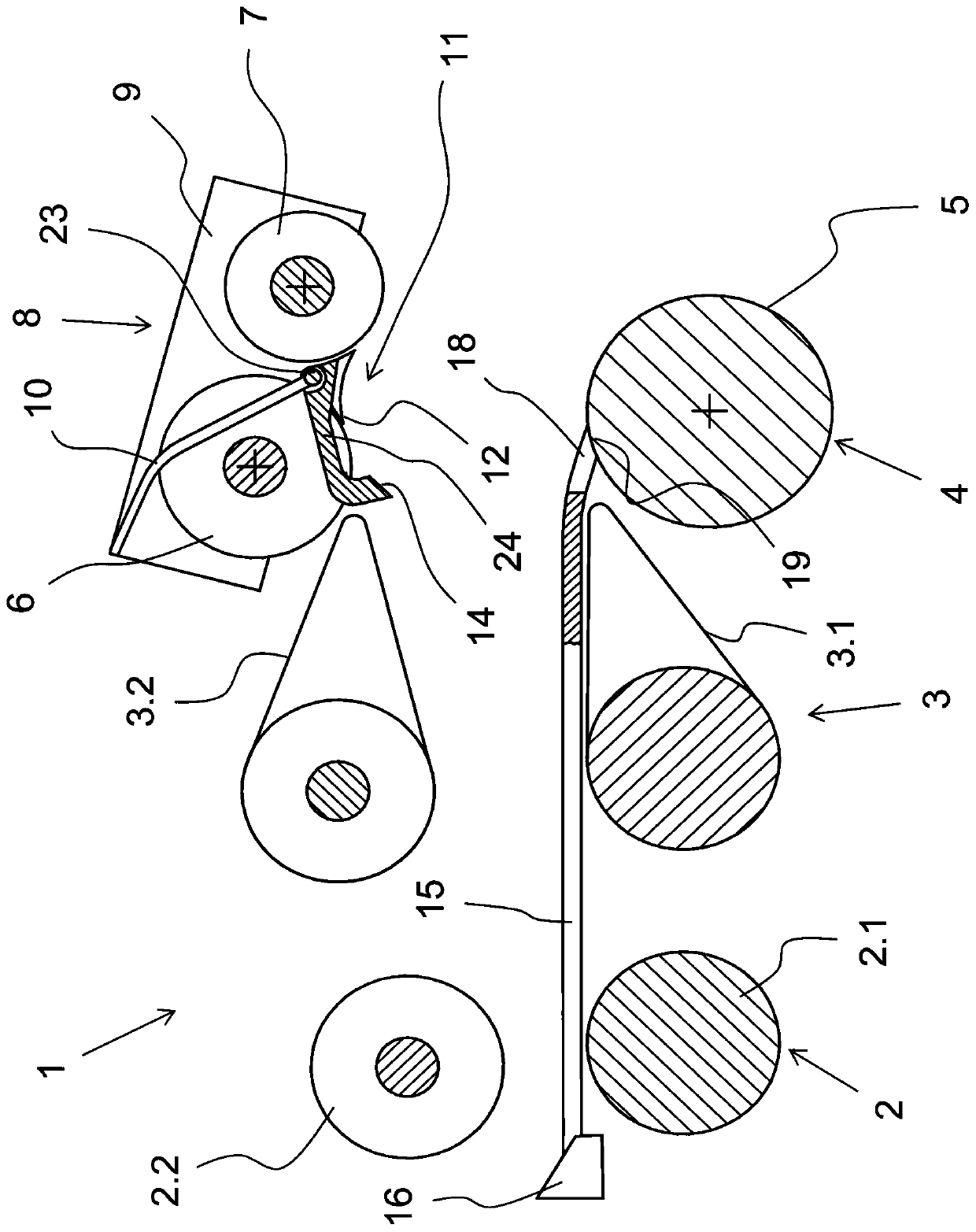
[0033] figure 1 A longitudinal section through a closed drafting system 1 according to the invention is shown. The drafting system 1 has a pair of input rollers 2 , a pair of drafting belts 3 and an output roller 4 . In the delivery roller 4 , the pressing roller 6 and the extraction roller 7 are arranged on the lower drafting roller 5 . In the closed drafting system 1 , the upper roller 2.2 of the input roller pair 2 , the upper belt 3.2 as well as the pressure roller 6 and the extraction roller 7 are located on the bottom roller 2.1 , the belt 3.1 and the drafting roller 5 .

[0034] Th...


PUM


Abstract

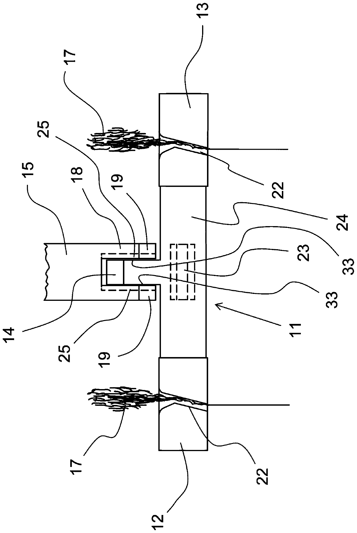
The invention relates to a compressor unit for two juxtaposed drafting systems (1) of a textile machine. The unit comprises a holding mechanism (24), on which a first joint surface (12) and a second joint surface (13) abutting a stretching roller (5) are arranged during operation of the stretching roller (5). Each joint surface (12, 13) is equipped with compression areas (22) to compress a fiber strip (17) vertically through the compression areas (22). The first joint surface (12) and the second joint surface (13) are spaced and transverse to compression areas (22) and connected with couplingelements used for a transversely-moving device. The transversely-moving device. enables a compression unit (11) to transversely move to the two compression areas (22). The compression unit (11) has athird joint surface (14). During operation of the drafting systems (1), the compression unit (11) is supported on the stretching roller (5). The third joint surface (14) is arranged between the firstjoint surface (12) and the second joint surface (13). The third joint surface and the compression area (22) are arranged in a staggered manner. The invention relates to a compaction roller unit (8) and the stretching systems (1) of the juxtaposed drafting systems (1), wherein the compression unit (11) is created aforementioned.

Description

technical field [0001] The invention relates to a compressor unit for two juxtaposed drafting systems of a textile machine, comprising a holding mechanism on which are arranged drafting rollers capable of abutting against the drafting systems during operation of said drafting systems. A first joint surface and a second joint surface, wherein each joint surface is arranged with a compression zone so as to be able to compress the fiber strip longitudinally passing through the compression zone, wherein the first joint surface and the second joint surface are transverse to each other in the compression zone spacing; and a coupling element for a traversing device that traverses the compressor unit transversely to the two compression zones. The invention also relates to a compaction roller unit with such a compressor unit and a drafting system with such a compaction roller unit. Background technique [0002] EP 1 953 275 B1 discloses a drafting system for drafting a fiber strip i...

Claims


Application Information

Patent Timeline
Patent Type & Authority Applications(China)
IPC IPC(8): D01H5/22D01H5/44D01H5/72D01H5/74
CPCD01H5/44D01H5/72D01H5/74D01H5/22
Inventor G·斯塔莱克G·沙夫勒K·胡贝尔
Owner MASCHINENFABRIK RIETER AG
Learn More