Power source protector
A technology of power protection and switching power supply, applied in the field of protection devices of switching power supply, can solve problems such as difficulty in distinguishing the cause of stop
- Summary
- Abstract
- Description
- Claims
- Application Information
AI Technical Summary
Problems solved by technology
Method used
Image
Examples
Embodiment approach 1
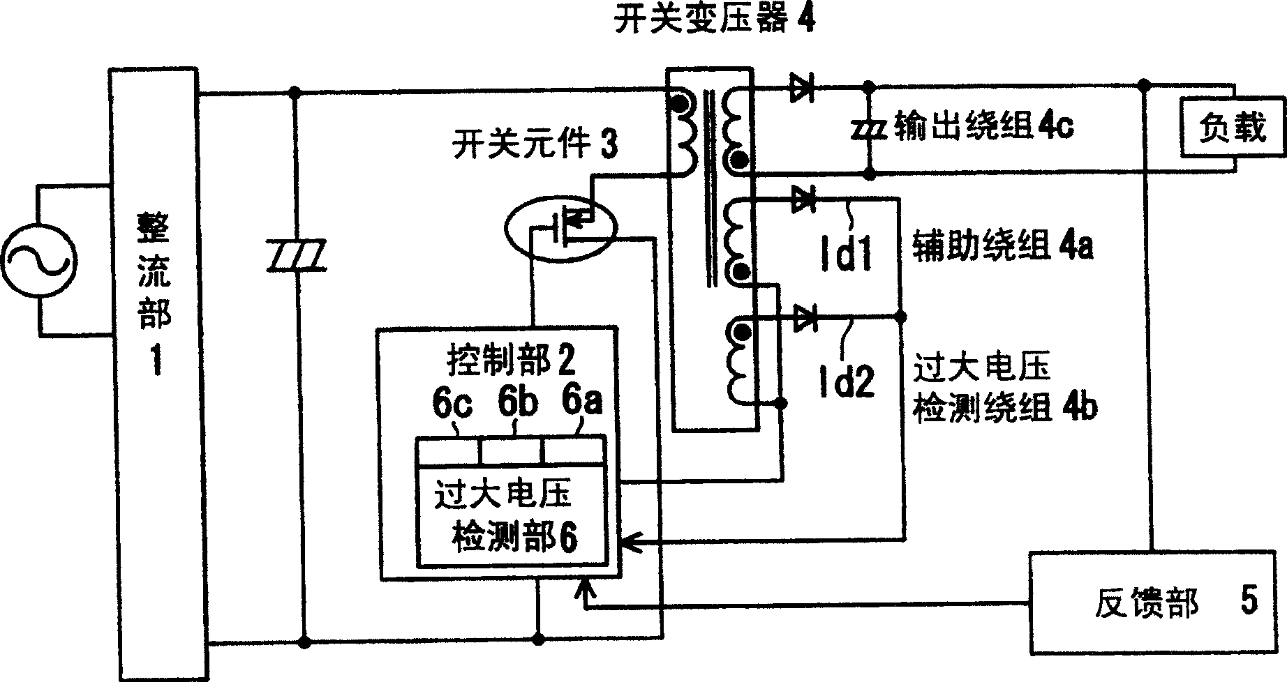
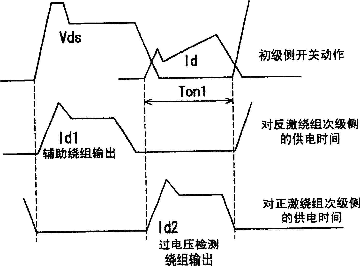
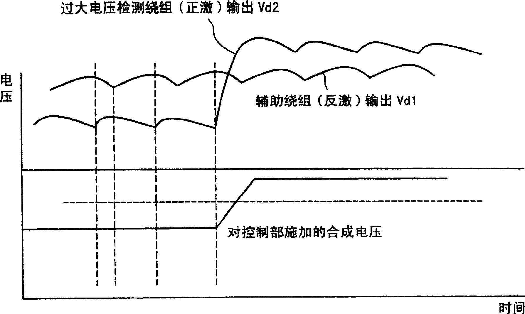
[0034] figure 1 is a configuration diagram of the power protection device in Embodiment 1 of the present invention, figure 2 is its representative action waveform diagram, image 3 It is a waveform chart showing an example of a change in the voltage applied to the excessive voltage detection unit. Hereinafter, for the configuration and operation of the power protection device according to Embodiment 1, refer to Figure 1 to Figure 3 Be explained.
[0035] The basic configuration of the power supply protection device according to Embodiment 1 is as follows: figure 1 As shown, it includes a flyback switch that is started by the rise of the DC voltage input on the primary side and continues the switching operation based on the voltage Vds generated by the output current Id1 of the auxiliary winding 4a of the switching transformer 4 fed back from the secondary side after the startup. power supply.
[0036] In Embodiment 1, the above-mentioned flyback switching power supply...
Embodiment approach 2
[0045] Figure 4 It is a configuration diagram of a power protection device according to Embodiment 2 of the present invention. Hereinafter, for the configuration and operation of the power protection device according to Embodiment 2, refer to Figure 4 Be explained.
[0046] exist Figure 4 In the power protection device according to Embodiment 2, an overvoltage detection unit 6 independent from the control unit 2 is provided, and the detection result of the output voltage is monitored by a microcomputer 7 which controls the device. For example, when an excessive voltage such as the voltage at the time of double voltage application is detected, all control is stopped, and the state becomes a standby state. In addition, it is a configuration in which an abnormal display such as blinking of a specific monitor LED is performed on the display unit 8 connected to the microcomputer 7 .
[0047] In Embodiment 1, when an excessive voltage is applied, the excessive voltage detecti...
Embodiment approach 3
[0052] Figure 5 It is a configuration diagram of a power protection device according to Embodiment 3 of the present invention. Hereinafter, for the configuration and operation of the power protection device according to Embodiment 3, refer to Figure 5 Be explained.
[0053] exist Figure 5 Among them, the power protection device according to Embodiment 3 is characterized in that it includes: an input unit 9 that makes the rectifier circuit 1 as a DC voltage generating circuit have a constant DC resistance value R; a bypass unit 10 that is connected in parallel with the input unit 9 Connections have transformation functions. The bypass unit 10 is controlled by the microcomputer 7 . According to such a configuration, when an excessive voltage such as a double voltage is applied, a voltage drop occurs in the DC resistance portion R of the input unit 9, and the input to the rectifier circuit 1 drops due to the voltage drop. That is, the voltage applied to the switching powe...
PUM
 Abstract
Description
Claims
Application Information
 - R&D
- Intellectual Property
- Life Sciences
- Materials
- Tech Scout
- Unparalleled Data Quality
- Higher Quality Content
- 60% Fewer Hallucinations
Browse by: Latest US Patents, China's latest patents, Technical Efficacy Thesaurus, Application Domain, Technology Topic, Popular Technical Reports.
© 2025 PatSnap. All rights reserved.Legal|Privacy policy|Modern Slavery Act Transparency Statement|Sitemap|About US| Contact US: help@patsnap.com


