Refrigerating system for heat pump air conditioner and its realizing method
A technology for refrigeration systems and air conditioners, applied in air conditioning systems, refrigerators, heating methods, etc., can solve problems such as inability to achieve both, inability to achieve refrigeration and heating, and reduce pressure loss and increase heat transfer coefficient. , the effect of increasing the refrigerant flow rate
- Summary
- Abstract
- Description
- Claims
- Application Information
AI Technical Summary
Problems solved by technology
Method used
Image
Examples
Embodiment 1
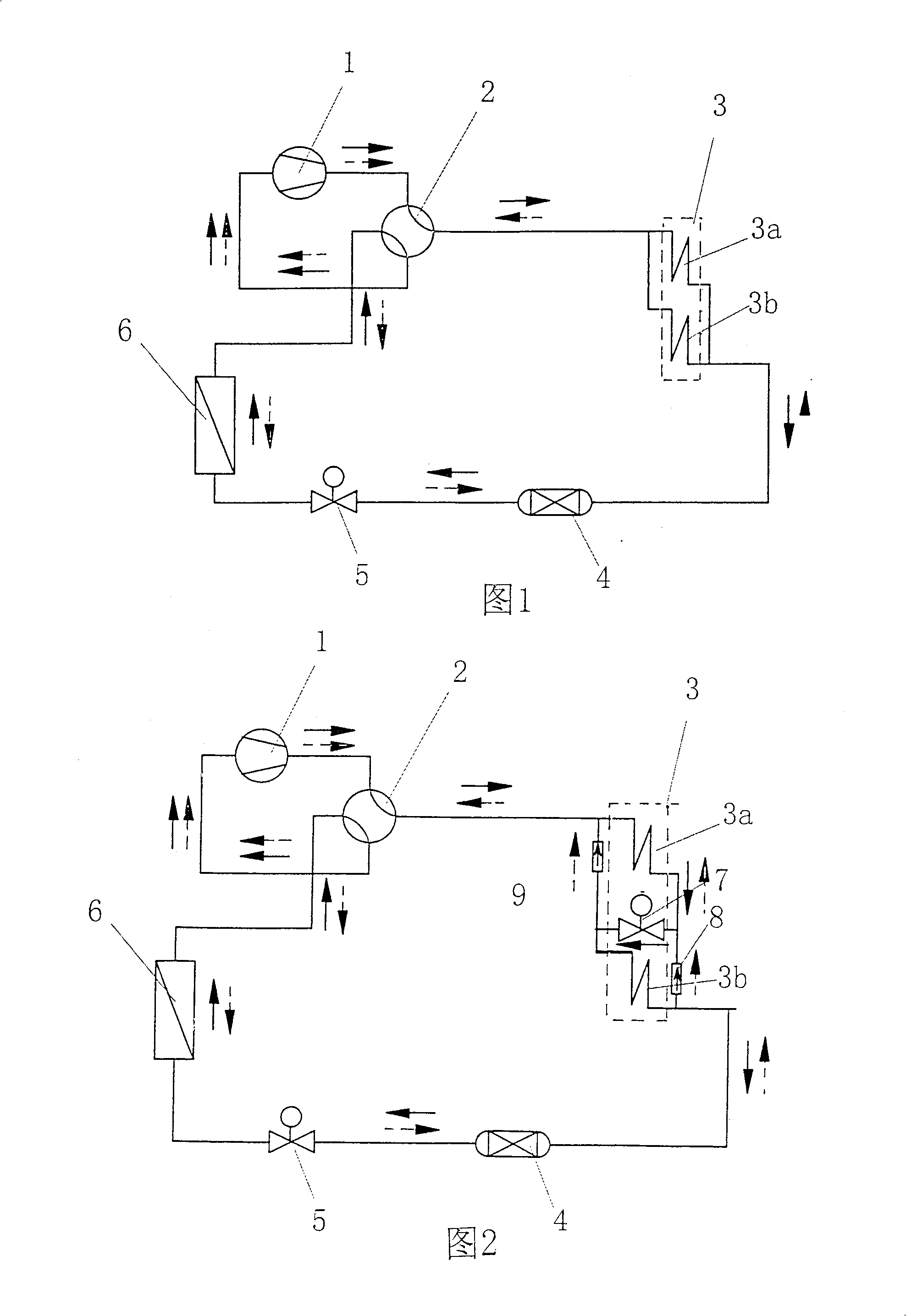
[0035]Figure 2 is a schematic diagram of Embodiment 1 of the present invention, and is specifically described by taking the outdoor heat exchanger as an example. In this embodiment, the outdoor radiator 3 is composed of two radiators 3a, 3b Composed, between the radiators 3a, 3b, a solenoid valve 7 is used to form a series pipeline. Among the two radiators 3a and 3b, the radiator 3a is the first sub-heat exchanger connected to the four-way reversing valve, so it is directly connected to the four-way reversing valve, while the other end is connected to the four-way reversing valve through a one-way reversing valve. The one-way valve 8 of the one-way valve is connected to the throttling device 5; the diffuser 3b is connected to the four-way reversing valve 2 through a one-way valve leading to the four-way reversing valve, because in this embodiment, the outdoor radiator 3 is composed of two radiators 3a and 3b, so the radiator 3b is the last sub-heat exchanger, therefore, the su...
Embodiment 2
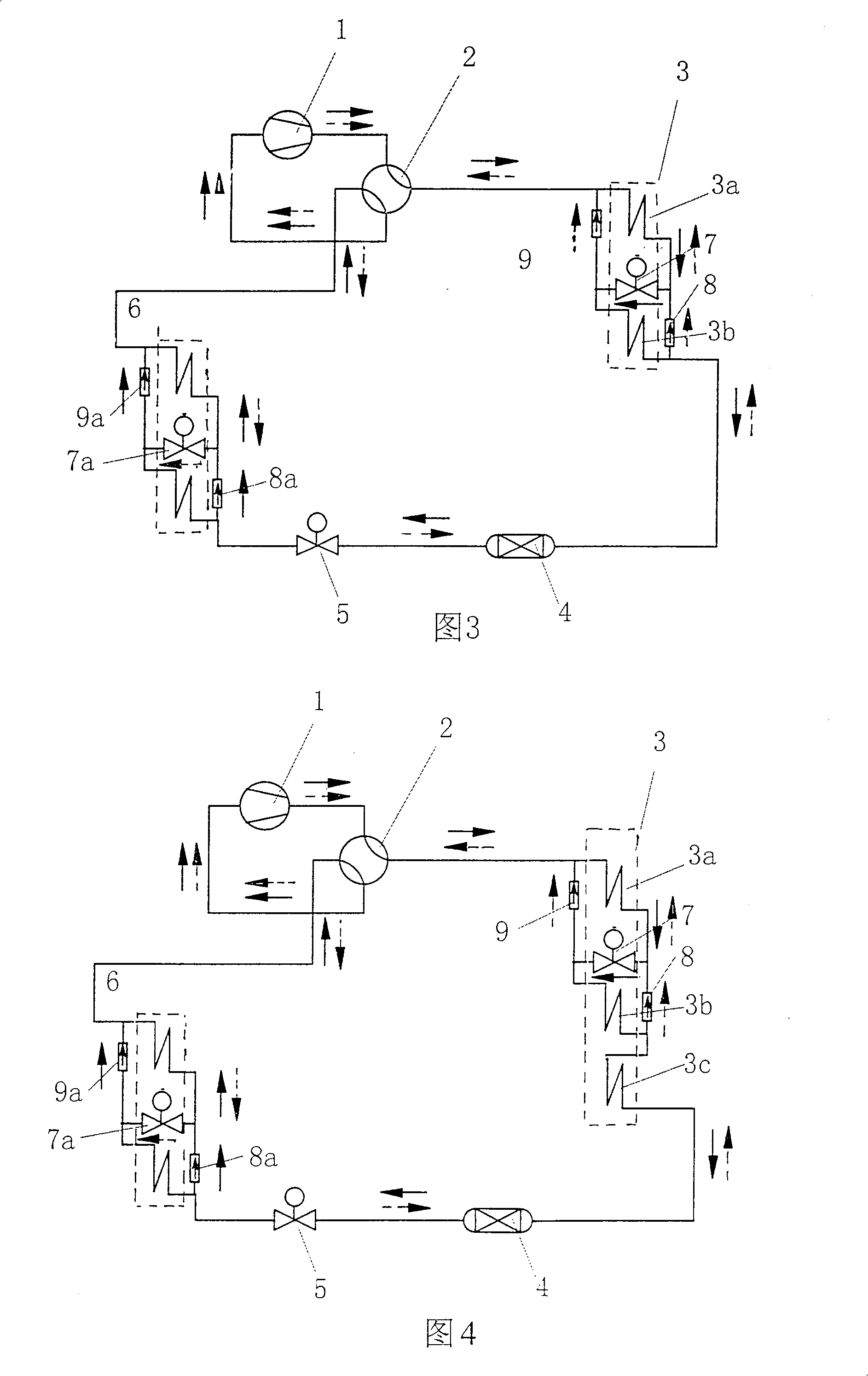
[0037] Fig. 3 is a schematic diagram of Embodiment 2 of the present invention, except that the same improvement is made on the outdoor side as in Embodiment 1, and the same improvement is also made on the indoor heat exchanger. In the present embodiment, the indoor side radiator 6 is also made up of two radiators 6a, 6b, and a solenoid valve 7a is used between the radiators 6a, 6b to form a series pipeline. In the two radiators 6a, 6b, The diffuser 6a is the first sub-heat exchanger connected to the four-way reversing valve, so it is directly connected to the four-way reversing valve, while the other end is connected through a one-way valve 8a leading to the four-way reversing valve Throttling device 5; radiator 6b then connects this four-way reversing valve 2 through a check valve leading to four-way reversing valve, because in the present embodiment, this indoor radiator 6 is made of two radiators 6a, 6b, so the diffuser 6b is the last sub-heat exchanger, therefore, the sub-...
Embodiment 3
[0039] Fig. 4 shows the schematic diagram of embodiment three of the present invention, and its difference with embodiment two is that the outdoor side radiator 3 is made up of three diffuser radiators 3a, 3b and 3c, between diffuser radiators 3a, 3b The solenoid valve 7 and the one-way valve form a series-parallel pipeline and then connect in series with the 3c diffuser to form another parallel pipeline connected between the four-way reversing valve and the throttling device.
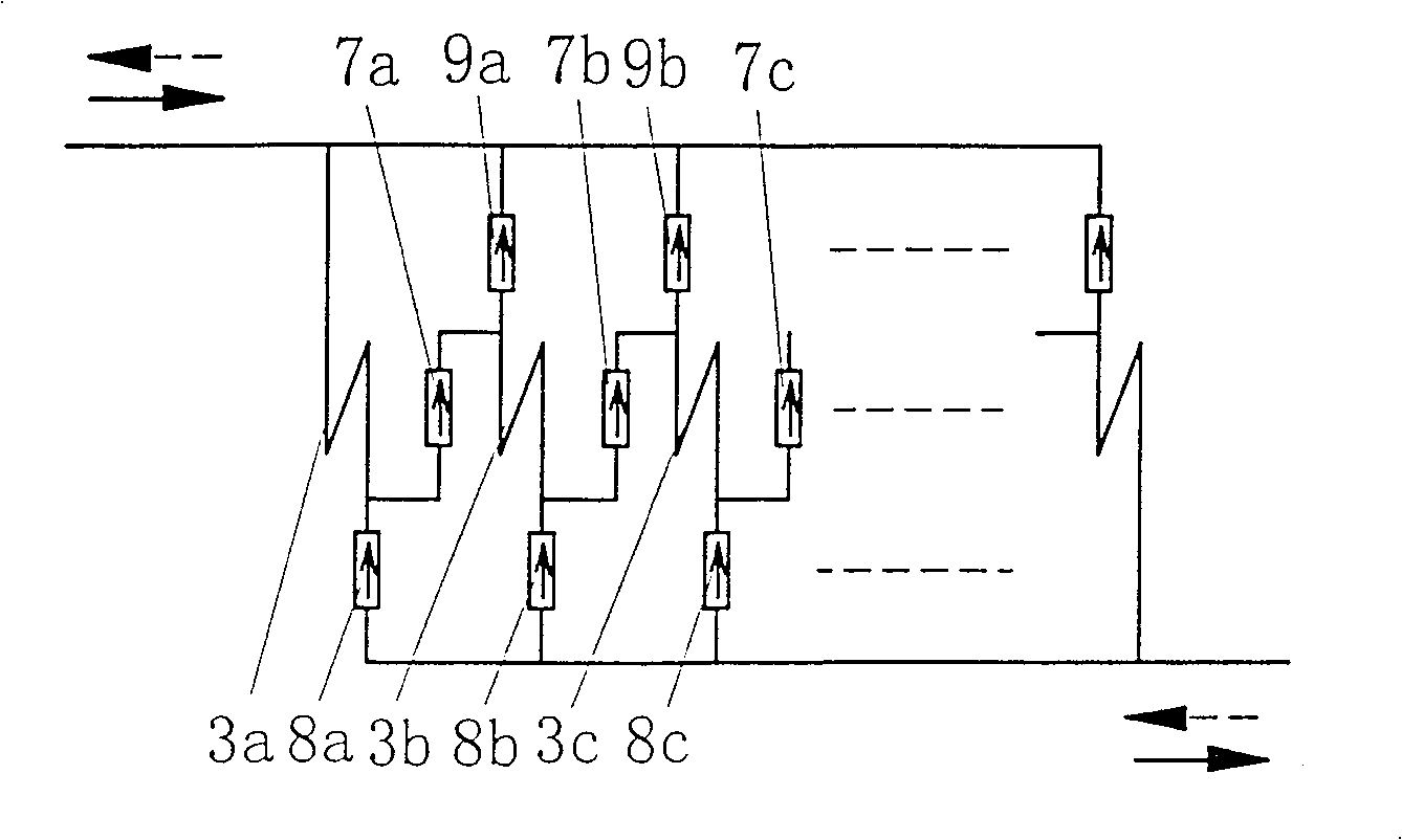
[0040] The above-mentioned embodiments are only a small part. It can be seen from the above-mentioned embodiments that the present invention mainly provides a method that can increase the refrigerant flow rate in the condensation process to increase the heat transfer coefficient, and in the heating process Among them, the implementation method of the refrigeration system of the heat pump air conditioner that reduces the flow rate of the refrigerant and reduces the pressure loss. The method is to set th...
PUM
 Abstract
Description
Claims
Application Information
 - R&D Engineer
- R&D Manager
- IP Professional
- Industry Leading Data Capabilities
- Powerful AI technology
- Patent DNA Extraction
Browse by: Latest US Patents, China's latest patents, Technical Efficacy Thesaurus, Application Domain, Technology Topic, Popular Technical Reports.
© 2024 PatSnap. All rights reserved.Legal|Privacy policy|Modern Slavery Act Transparency Statement|Sitemap|About US| Contact US: help@patsnap.com


