
Driving panel welding method for golf pole head

A golf club head and welding method technology, applied to golf balls, golf clubs, welding equipment, etc., can solve problems such as inability to apply the striking panel 20, inability to effectively increase friction temperature, structural fragmentation, etc.

Inactive Publication Date: 2009-07-22
FUSHENG IND CO LTD
View PDF6 Cites 0 Cited by
  • Summary
  • Abstract
  • Description
  • Claims
  • Application Information

AI Technical Summary

Problems solved by technology

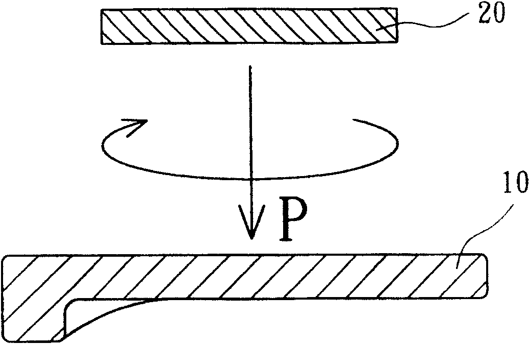
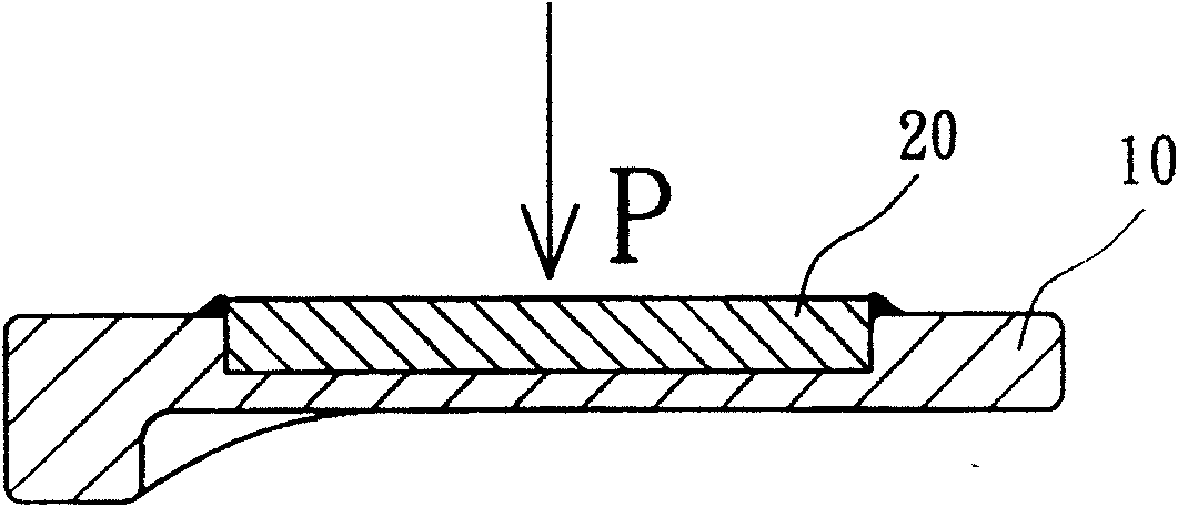
[0005] Although the friction welding method of the golf club head can simplify the manufacturing process and improve the bonding quality compared with the above-mentioned other bonding methods, the friction welding method still has the following problems: since the hitting panel 20 must rotate relative to the club head body 10, the hitting Panel 20 can only form a perfect circular shape, which cannot be used in conjunction with a non-circular strike panel 20; in addition, this strike panel 20 can only form a small hitting area, that is, its sweet spot (sweet spot) range is relatively large. Furthermore, if the contact area of ​​the friction abutment surface of the hitting panel 20 and the club head body 10 is too large or its surface has an oxide layer, it often results in the inability to effectively increase the friction temperature, so that when the friction welding is combined by An intermetallic layer (or hardened layer) is produced between the two
In particular, when the welding compatibility of the metal material of the hitting face plate 20 and the club head body 10 is insufficient, the characteristics of the intermetallic layer will not be conducive to improving the bonding strength, and will easily cause structural fragmentation or reduce elastic deformation capacity.
Based on the above-mentioned shortcomings, the size of the strike panel 20 is often unable to expand and is limited

Method used


Image

  • Driving panel welding method for golf pole head
  • Driving panel welding method for golf pole head
  • Driving panel welding method for golf pole head

Examples


Embodiment Construction

[0028] Please refer to figure 2 and image 3 As shown, the first step of the welding method for the hitting face plate of the golf club head according to the first embodiment of the present invention is to set a friction welding slope 21 on a hitting face plate 20, and set another correspondingly in an opening 11 of a club head body 10. A friction welded bevel 12 . The golf club head of the present invention is an iron club head, and its structure at least includes the club head body 10 , the first friction welding bevel 12 , the striking face plate 20 and the second friction welding bevel 21 . The club head body 10 is made of a first metal material, and the first metal material can be selected from stainless steel, titanium alloy, carbon steel, low alloy steel, cast iron, nickel-based alloy, structural steel, iron-manganese-aluminum alloy or super alloy steel. The opening 11 is formed on the front of the club head body 10 for inserting the striking panel 20 . The first f...


PUM


Abstract

The present invention is the welded structure and method for the stroking panel of golf club head. The welding process includes the following steps: setting friction welding slant in the stroking panel and setting one corresponding friction welding slant inside the opening of the golf club head; combining these two friction welding slants; applying one force onto the stroking panel to make the stroking panel embedded closely into the opening; completing friction welding in the contact surfaces of the stroking panel and the golf club head body with one rotating unit; and completing the surface processing of the welded part to finish the golf club head.

Description

technical field [0001] The present invention relates to a welding method of a golf club head striking face plate, in particular to a method of setting a friction welding slope on a striking face plate and correspondingly setting another friction welding slope on a club head body so as to increase the reliability of friction welding. Background technique [0002] Nowadays, the design of golf club heads tends to form composite materials, especially the club head body and striking panel are usually made of different metal materials, for example, the club head body is made of 17-4PH stainless steel and the strike is made of 6 aluminum-4 vanadium titanium alloy. The panel, so that the golf club head can have both a high structural strength club head body and a high elastic deformation ability hitting panel. [0003] Although the design of the above-mentioned composite material can improve the hitting performance of the golf club head, it is relatively difficult to form a good joi...

Claims


Application Information

Patent Timeline
IPC IPC(8): B23K20/12A63B53/02A63B102/32
Inventor 陈建同
Owner FUSHENG IND CO LTD
Learn More