A method for equable glue filling of LED and corresponding glue filler

A technology of light-emitting diodes and glue filling machines, applied in the field of glue filling machines, can solve the problems of difficult control of gap accuracy, influence of glue injection uniformity, large gap, etc., to achieve the effects of reducing difficulty, enhancing sealing and increasing work efficiency

Inactive Publication Date: 2009-04-15
杨少辰
View PDF2 Cites 0 Cited by
  • Summary
  • Abstract
  • Description
  • Claims
  • Application Information

AI Technical Summary

Problems solved by technology

Since the glue filling machine uses a cylindrical rotating rod to inject glue, due to the limitation of its inherent mechanical structure, the gap between the base that can rotate the cylindrical rotating rod and the cylindrical rotating rod is very small. Large, and the gap accuracy is difficult to control, which also affects the uniformity of the injected glue

Method used


Image

  • A method for equable glue filling of LED and corresponding glue filler
  • A method for equable glue filling of LED and corresponding glue filler
  • A method for equable glue filling of LED and corresponding glue filler

Examples


Embodiment Construction

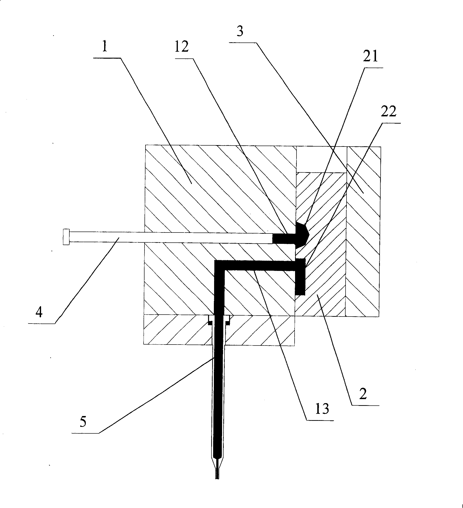
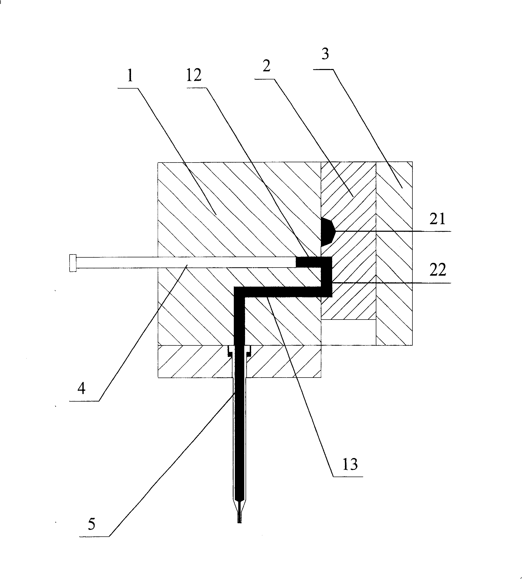
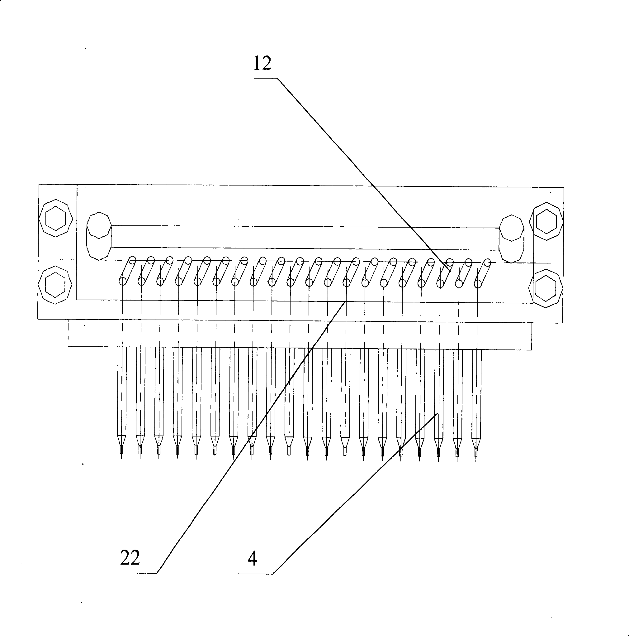
[0037] The present invention proposes a method for uniformly pouring glue on light-emitting diodes, please refer to figure 1 with figure 2 , Is the longitudinal section view of the glue pouring machine. The glue pouring machine includes a body 1 and a valve plate 2, and an elastic plate 3 is fixed on the plate surface of the valve plate 2, which is used to compress the valve plate and maintain the valve plate. The airtightness between the plate surface and the side surface of the body; a set of piston rods 4 are connected to the power source of the stepping motor, the piston rod 4 reciprocates with the power source, and the piston rod 4 is sleeved in the material storage in the body 1 In hole 12, a feed orifice is arranged on the body, and the other end of the feed orifice is located on the side of the body; the side of body 1 is provided with a valve plate 2 that can move up and down. The valve plate 2 contains a groove 21 and a pipe. 22. The conduit 22 is located below the gro...


PUM


Abstract

The invention is concerned with the glue filling machine and the glue filling method for the light-emitting diode, it includes: the engine block (-) with the blanking hole (-) under the storing hole (-); the piston gear (-) connecting with the power source (-); the storing hole (-) attaches with the piston gear (-) where the opening on the side of the engine block that connects with the flow entering hole; there-into the flute (-) and the canal (-) below are in the valve board (-)on the side of the engine block; the valve board controls the operation by moving to the storing hole (-) of the flute (-) that than detaches with the canal leading the connection between the valve board (-) and the flute (-); or moving backwards to detach the storing hole (-) with the flute (-) of the valve board (-) that leads the connection between the canal (-) and the blanking hole (-). The invention insures the equality of the LED glue filling partly and improves its quality and its productivity.

Description

Technical field [0001] The invention relates to the technical field of electromechanical integration, in particular to a method for uniformly pouring glue on LEDs, and a corresponding glue pouring machine using the method. Background technique [0002] At present, the widely used LED glue potting machine mainly includes an upper cover, an actuating rod, a base, and a gluing table. Wherein, the cover cloth is provided with a plurality of inlet diversion holes for inputting rubber; the actuating rod is provided with a plurality of straight glue holes and transverse holes communicating with the straight glue holes, and The hole end of the transverse hole is provided with a wider groove; the base is provided with a chute that can accommodate the actuating rod, and the bottom and the side of the groove are also provided with a plurality of feeding holes and storage holes, and each storage hole They are fitted with a corresponding piston rod; the glueing table is used to cooperate with...

Claims


Application Information

Patent Timeline
Patent Type & Authority Patents(China)
IPC IPC(8): H01L33/00H01L21/56B29C39/10H01L33/52H01L33/54
Inventor 杨少辰韩金龙罗会才李新贵
Owner 杨少辰
Why Eureka
Try Eureka