
Compound processing machinery

A composite processing and composite tool technology, applied in metal processing machinery parts, metal processing, metal processing equipment and other directions, can solve the problems of low sub-processing efficiency, achieve the effect of easy management and avoid interference

Inactive Publication Date: 2009-04-15
YAMAZAKI MAZAK KK
View PDF5 Cites 2 Cited by
  • Summary
  • Abstract
  • Description
  • Claims
  • Application Information

AI Technical Summary

Problems solved by technology

[0003] Such a working machine must have the action of changing the tool according to the change of the processing content, and it takes time to change the tool, and there is a defect that the processing efficiency is low.

Method used


Image

  • Compound processing machinery
  • Compound processing machinery
  • Compound processing machinery

Examples


Embodiment Construction

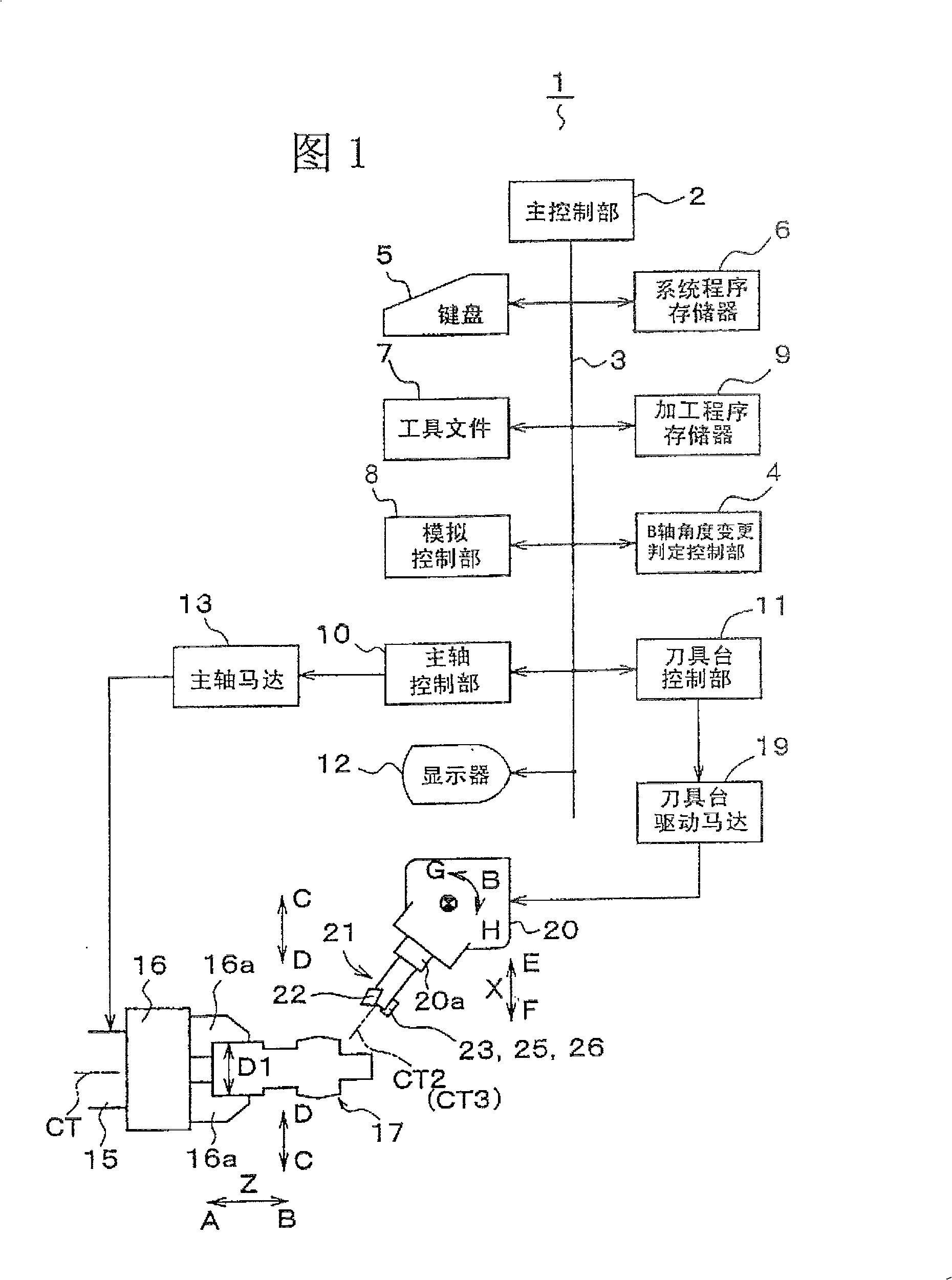
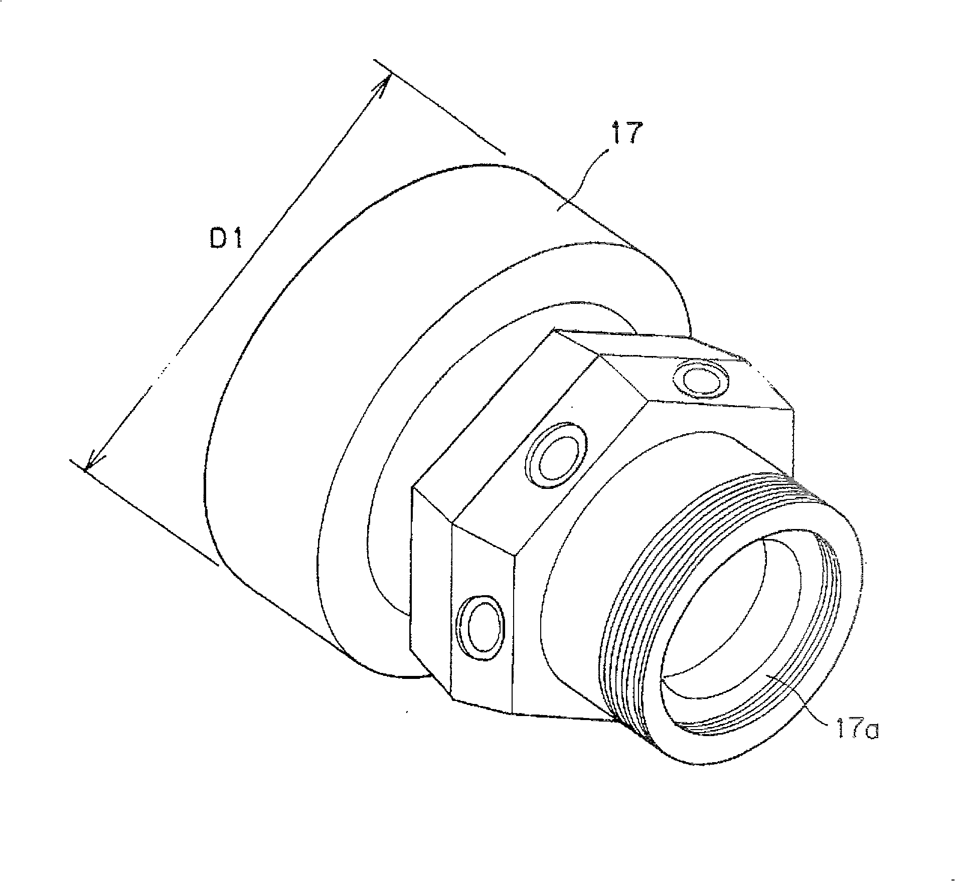
[0031] As shown in Figure 1, a compound processing machine (machine tool) 1 is provided with a main control unit 2, and the main control unit 2 is provided with input units such as a bus 3 and a keyboard 5, a system program memory 6, a tool file 7, a simulation control unit 8, and a processing program. The memory 9, the B-axis angle change determination control unit 4, the spindle control unit 10, the tool post control unit 11, and the display 12 are connected. The spindle motor 13 is connected to the spindle control unit 10 . Centering on the axis CT parallel to the Z-axis, the freely rotatable, drive-positioned spindle 15 is connected to the spindle motor 13 , and the chuck 16 is arranged on the spindle 15 . Claws 16a are provided on the chuck 16, and the claws 16a can freely grasp or release the workpiece 17 to be processed, and are freely driven to move in the arrow C, D directions.

[0032] The tool rest drive motor 19 (multiple) is connected on the cutter rest control p...


PUM


Abstract

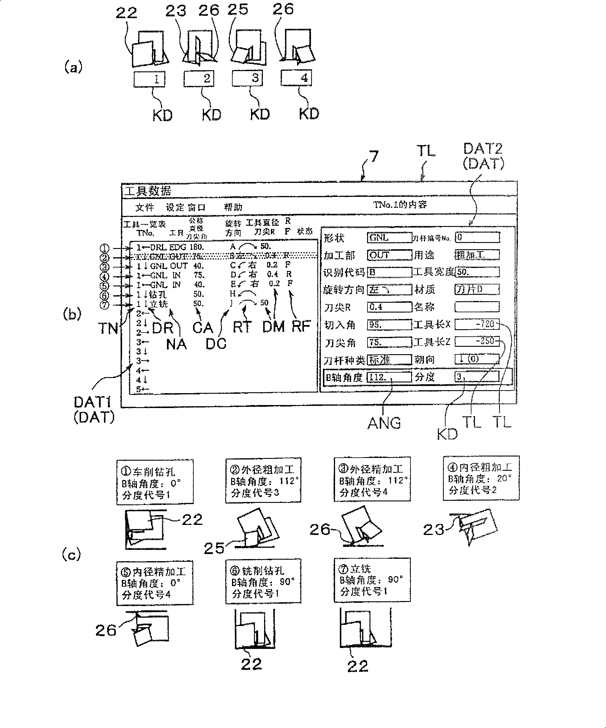
In a complex machining machine tool capable of executing a plurality of kinds of machining on a workpiece by selectively indexing and using an insert installed on a complex tool, complex tool is registered concerning a plurality of machining capable of executing with the complex tool as a plurality of virtual tools for executing the machining in tool file. The virtual tools include a turning tool and a milling tool. The tool data is stored for each virtual tool. In the tool data, the angle of B-axis direction at which the tool is positioned when the virtual tool is used is stored as B-axis angle concerning each virtual tool. The tool data of the corresponding virtual tool is read out from the tool file on the basis of the machining instruction by the virtual tool stored in machining program, and the B-axis angle is set on the basis of the tool data so as to execute machining.

Description

technical field [0001] The present invention relates to a composite processing machine (machine tool) using a composite tool having a plurality of blades mounted on a single shank portion, and which can perform rotary tool processing such as turning processing and drilling / milling processing with a single tool. Background technique [0002] The tools of such existing machine tools are divided into turning tools and drilling / milling tools. As the processing content changes, the tools mounted on the tool table are detached and replaced to adapt to the processing to be performed. thereby processing. [0003] Such a working machine must have the action of changing the tool according to the change of the processing content, which requires time for changing the tool, and has the disadvantage of low processing efficiency. Someone recently proposed the technical scheme of using a compound tool with multiple blades on a single tool, which can save the trouble of changing tools and i...

Claims


Application Information

Patent Timeline
Patent Type & Authority Patents(China)
IPC IPC(8): B23P23/00G05B19/4093B23Q15/00B23B51/04B23C5/02B23P23/02B23Q3/155G05B19/4065G05B19/4069
CPCG05B2219/33131G05B2219/36276G05B19/4065B23B51/04G05B2219/36362B23Q3/155B23B2270/56G05B19/40938G05B2219/49376G05B2219/36071G05B2219/37252G05B19/40937G05B2219/35316Y02P90/02Y10T82/2502Y10T82/2533
Inventor 山崎恒彦福村直慧水门正良木方一博宫嵜贞美牧浩一
Owner YAMAZAKI MAZAK KK
Learn More