Integrated surge current limiter circuit and method

A technology of limiter circuit and inrush current, applied in the direction of emergency protection circuit device, circuit device, emergency protection circuit device for limiting overcurrent/overvoltage, etc. issues of sex

Inactive Publication Date: 2009-03-18
SEMICON COMPONENTS IND LLC
View PDF4 Cites 0 Cited by
  • Summary
  • Abstract
  • Description
  • Claims
  • Application Information

AI Technical Summary

Problems solved by technology

[0003] The disadvantage of existing inrush current limiters is that they are too expensive due to the large number of components required to control the power MOSFET switches to limit the inrush current to a specified level
Most inrush current limiters use a low value sense resistor in series with the power MOSFET switch to limit the peak value of the power supply
However, the high power dissipation caused by the large currents flowing through the switch and sense resistor can negatively impact reliability

Method used


Image

  • Integrated surge current limiter circuit and method
  • Integrated surge current limiter circuit and method
  • Integrated surge current limiter circuit and method

Examples


Embodiment Construction

[0012] In the figures, elements with the same reference numbers have the same function.

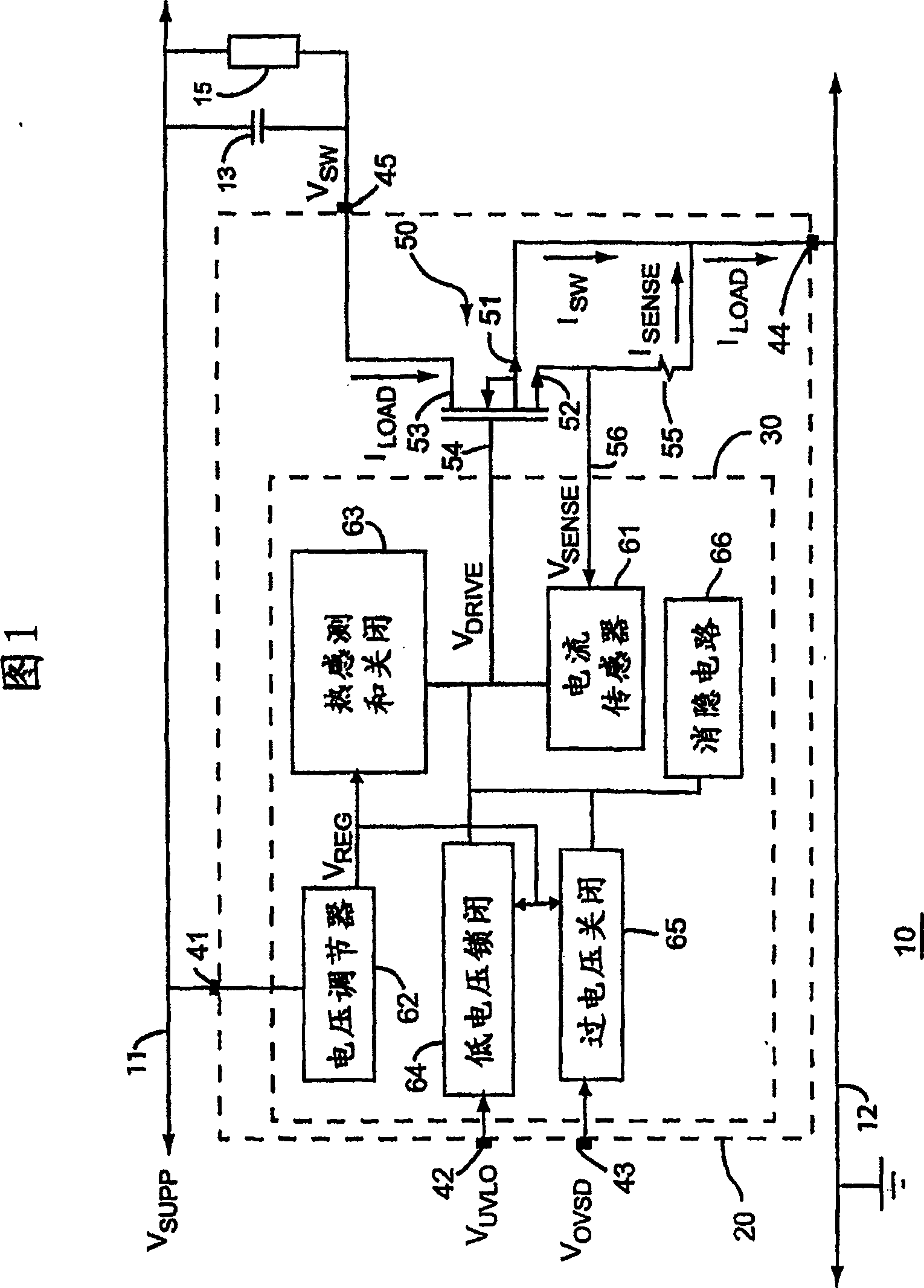
[0013] FIG. 1 is a simplified schematic diagram of a hot swappable circuit card 10 for use when operating at a supply voltage V SUPP = 48.0 Volts during plugging and / or unplugging from the electronic system while power is applied between distributed power bus 11 and ground node 12 . The power bus 11 and the ground node 12 can simultaneously provide power to other components (not shown) of the electronic system.

[0014] A large filter capacitor 13 smoothes noise spikes on the power bus 11 to provide a stable bias voltage. The circuit performing the function of the circuit card 10 is represented as a load 15 which draws a load current I from the power bus 11 through an inrush current limiter circuit 20 LOAD . In one embodiment, load 15 includes a voltage regulator that obtains I LOAD = 10.0 amps of load current as a peak through capacitor 13 and load 15 . I LOAD A typical average is ...


PUM


Abstract

A kind of inrush current limiter circuit (20) comprises detection circuit (30), and it according to sensing current (I SENSE ) to generate a control signal (V DRIVE ). The power transistor is responsive to the control signal and has a source (51) coupled to an input node (12) to receive a supply voltage (ground) and for directing a load current (I LOAD ) to the output node (45) as a guard signal (V SW ) of the drain (53). A sense transistor is responsive to the control signal and has a source proportional to the source of the power transistor and is coupled to the input node for directing a portion of the load current to the output node as a sense current.

Description

technical field [0001] The present invention relates generally to semiconductor devices, and more particularly to high current devices for limiting current surges on power supply buses. Background technique [0002] Communications, networking, and computer applications often require the ability to insert or remove circuit cards from a system without powering down the entire system, commonly referred to as "hot swapping." In network equipment equipped with distributed power systems, circuit cards often include large filter capacitors to reduce noise on the rails or buses. During the heat-swapping process, this capacitor can generate inrush current spikes that can reach hundreds of amps if not otherwise limited, which can destroy the circuit card or its connectors. Also, the power disturbances that such large inrush currents can generate can destroy other circuit cards plugged into the system, or cause data loss or other system failures. To prevent this deleterious effect, t...

Claims


Application Information

Patent Timeline
Patent Type & Authority Patents(China)
IPC IPC(8): H02H9/00H02H1/00
CPCH02H1/0007H02H9/001H02H9/02H02H9/00H02H3/00
Inventor 阿兰·巴尔大卫·布里格斯苏珊·尼斯蒂芬·罗博
Owner SEMICON COMPONENTS IND LLC
Why Eureka
Try Eureka