Detection method for blood pressure monitor with korotkoff sound delaying and pulse wave conducting time, and signal generator applying the same
A technology of conduction time and signal generating device, which is applied in the direction of cardiac catheterization, etc., and can solve problems such as not being able to meet the mutual coordination of blood pressure monitors
- Summary
- Abstract
- Description
- Claims
- Application Information
AI Technical Summary
Problems solved by technology
Method used
Image
Examples
Embodiment 1
[0039] This example is a kind of device that adopts the method of the present invention-the Korotkoff sound delay time and pulse wave transit time signal generator.
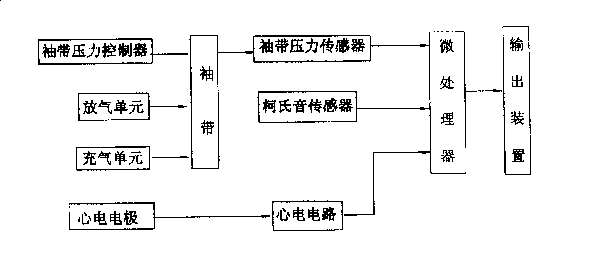
[0040] The structure of this device is as Figure 4 Shown: There is a central control single-chip microcomputer, a memory for storing data including ECG, pulse wave, respiration, and Korotkoff sound waveforms. The single-chip microcomputer is connected to the analog signal output of the human body through a digital / analog converter and a signal conditioning circuit. ;
[0041] The structure of the cuff pulse wave pressure signal generating device in this example is as follows: an air storage device is provided, its input end is connected with an inflatable motor controlled by a single-chip microcomputer, and the output end is connected with the cuff through an air circuit switch controlled by a single-chip microcomputer.
[0042] The generation method of physiological signal adopting this device is:
[0043] Re...
Embodiment 2
[0047] This example is several specific implementation working modes of the method of the present invention.
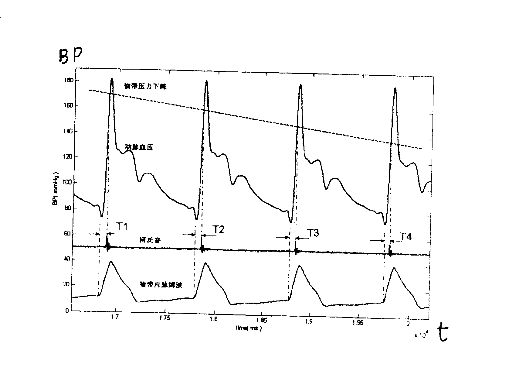
[0048] Aiming at several main detection processes of blood pressure monitoring using Korotkoff sound delay time and pulse wave transit time disclosed in ZL200510071813.0 and PCT / CN2005 / 001210 patent applications, this example sets several working modes suitable for different detection processes. The following describes them one by one:
[0049] 1. This working mode is aimed at the following detection process of the blood pressure monitor: After the blood pressure monitor obtains the PWTT coefficients a and b in the calculation formula, it calculates the blood pressure value BP by measuring PWTT.
[0050] 1-1. Brief description of the detection process of the blood pressure monitor:
[0051] According to the relationship between PWTT and beat-by-beat arterial blood pressure BP:
[0052] BP=a+b*PWTT...(A)
[0053] Where BP is arterial blood pressure, PWTT is pulse wa...
Embodiment 3
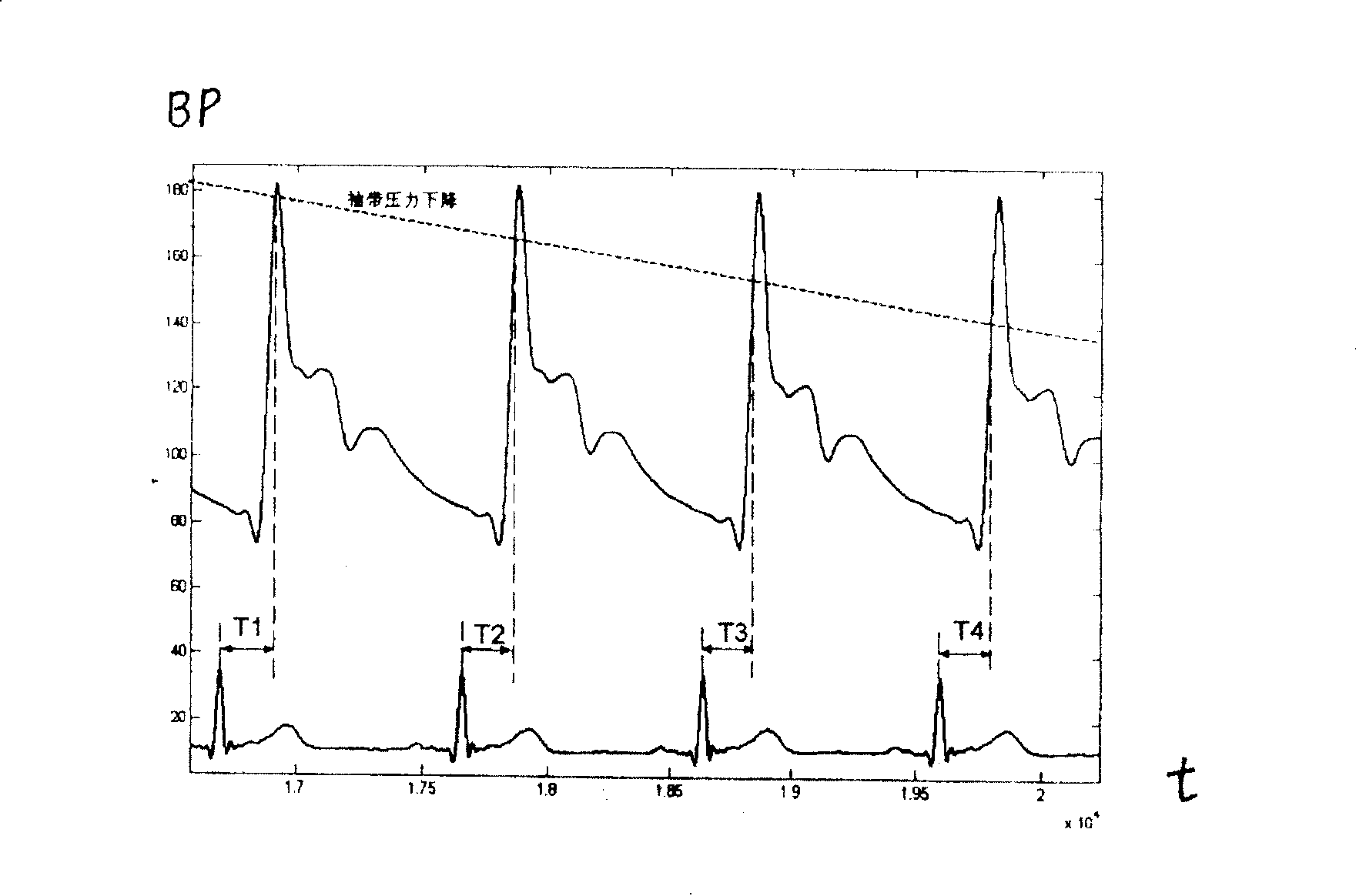
[0090] The difference from Embodiment 2 is that in the 2-2 working mode, Embodiment 2 expresses the Korotkoff sound delay time T by the time interval from the cuff pulse wave starting point to the Korotkoff sound arrival moment K In this example, the Korotkoff sound delay time T is expressed by the time interval from the peak value of the ECG R wave to the moment when the Korotkoff sound arrives. K signal (see figure 1 ), start timing from the peak value of the ECG R wave, and output the starting point and subsequent waveforms of the Korotkoff sound signal when the Korotkoff sound delay time of the set blood pressure is reached.
[0091] In this example, the relationship curve T between the Korotkoff sound delay time and blood pressure K (P) Stored in the computer, the setting method is: describe the relationship curve T between the Korotkoff sound delay time and blood pressure through several parameters and an equation K (P), stored in the known curve T in advance K (P) eq...
PUM
 Abstract
Description
Claims
Application Information
 - R&D Engineer
- R&D Manager
- IP Professional
- Industry Leading Data Capabilities
- Powerful AI technology
- Patent DNA Extraction
Browse by: Latest US Patents, China's latest patents, Technical Efficacy Thesaurus, Application Domain, Technology Topic, Popular Technical Reports.
© 2024 PatSnap. All rights reserved.Legal|Privacy policy|Modern Slavery Act Transparency Statement|Sitemap|About US| Contact US: help@patsnap.com


