Super conducting energy saving desalination drinking water making system of ocean ship

A drinking water device and superconducting technology, applied in fresh water production devices, ship construction, seawater treatment and other directions, can solve the problems of inconvenience of crew and passengers, waste of limited energy of ships, and occupy precious space of ships, etc., to reduce load and simple structure. , the effect of improving utilization

Inactive Publication Date: 2009-02-18
何诺
View PDF7 Cites 2 Cited by
  • Summary
  • Abstract
  • Description
  • Claims
  • Application Information

AI Technical Summary

Problems solved by technology

[0002]At present, drinking water on ocean ships is mainly supplied by fresh water reserves, which requires huge water storage tanks, which not only takes up valuable space on the ship but also increases the load on the ship. Aggravating and wasting the limited energy of sailing
Not only that, due to the limited water storage, the supply of fresh water on board is greatly restricted, causing great inconvenience to the crew and passengers

Method used


Image

  • Super conducting energy saving desalination drinking water making system of ocean ship
  • Super conducting energy saving desalination drinking water making system of ocean ship
  • Super conducting energy saving desalination drinking water making system of ocean ship

Examples


Embodiment 1

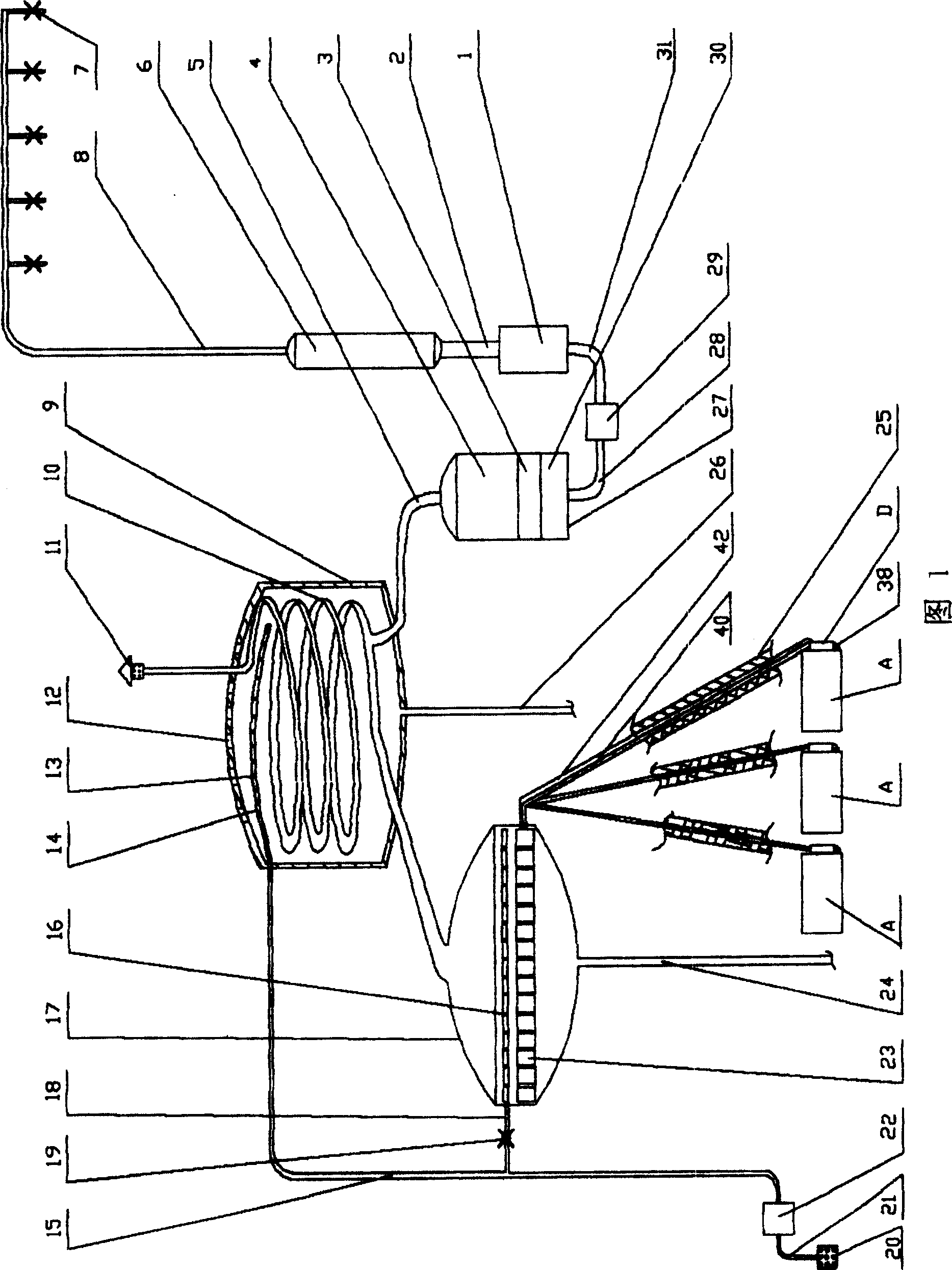
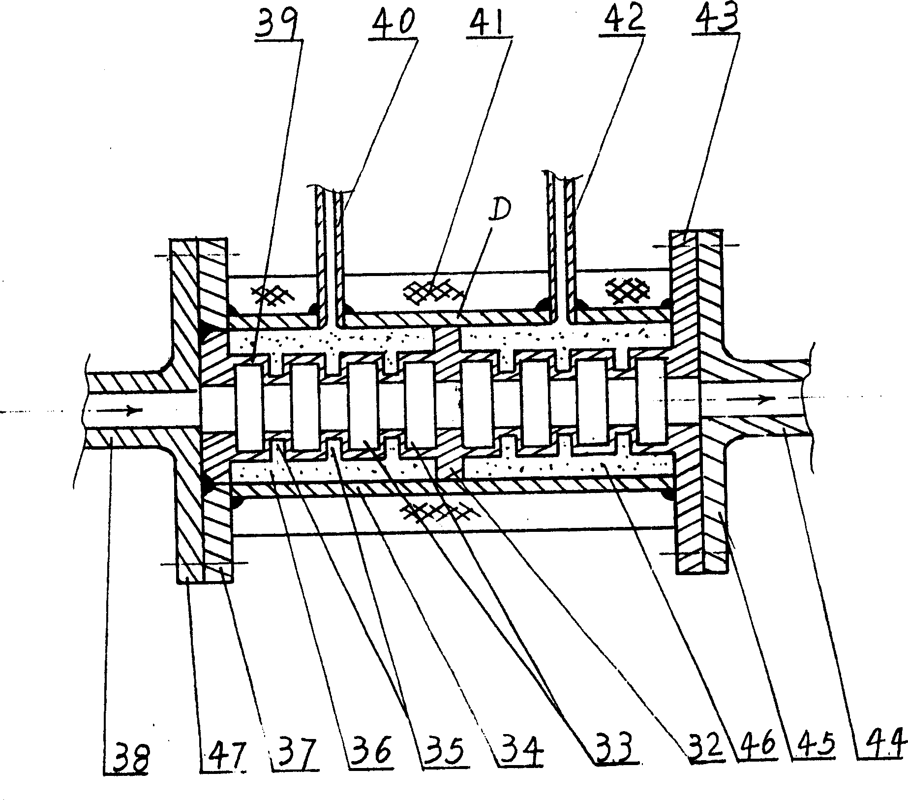
[0015] Embodiment 1: as shown in Figure 1, figure 2 As shown, a superconducting heat collecting tube D is installed on the exhaust port of the internal combustion unit A, and the superconducting heat collecting tube D and the superconducting heat pipes 40, 42 are integrally structured, and the superconducting heat collecting tubes D on the superconducting heat collecting tube 40, 42 is connected on the cooling plate 23 in the reaction tank 17, the spray pipe 18 is equipped with on the top of the cooling plate 23, the top of the reaction tank connects the disc cooling pipe 10, and the disc cooling tube 10 is contained in the cooling tank 9. The top of the cooling tank 9 has cooling holes 12 to communicate the cooling tank with the outside atmosphere, and the top of the cooling tank 9 is equipped with a shower pipe 14 . The top of the disc-shaped cooling pipe 10 is an exhaust port 11, and the bottom of the disc-shaped cooling pipe 10 is equipped with a water receiving pipe 5, wh...

Embodiment 2

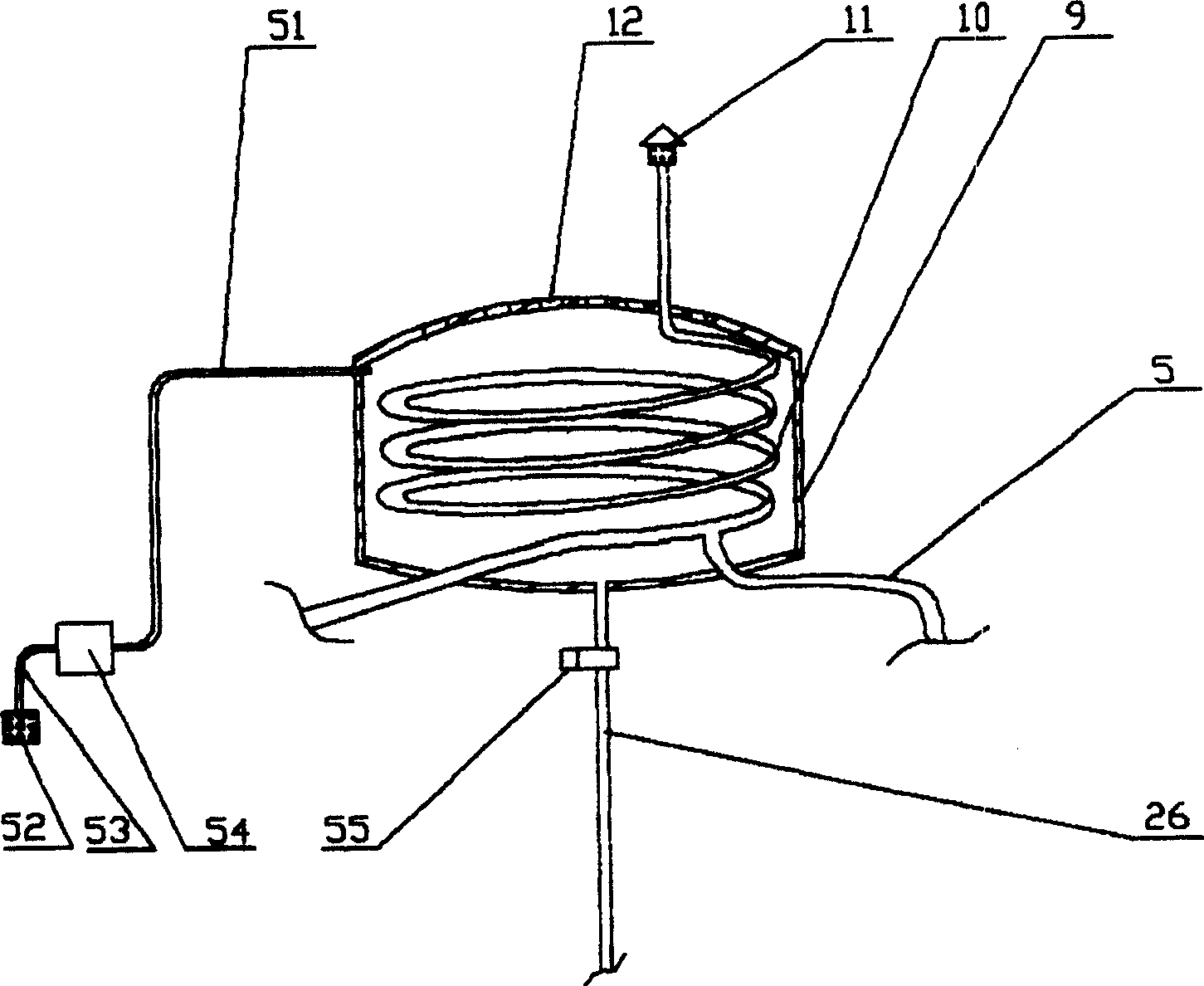
[0020] Embodiment 2, this embodiment is basically the same as Embodiment 1, as image 3 As shown, only the spray pipe is not installed in the cooling tank 9, but a water pump 51 is arranged to extract the seawater through the water inlet pipe 51 and directly send it into the cooling tank 9, so that the cooling tank 9 is filled with seawater, and the seawater directly sprays the disc cooling tube. 10 cool down. On the drain pipe 26 below the cooling tank 9, an electric regulating valve 55 is additionally installed to control the amount of draining water, so that the cooling tank 9 is always filled with seawater for improving the cooling effect. Of course, the cooling tank 9 can also be omitted, and the disc-shaped cooling pipe 10 is placed in the air to allow the sea breeze to cool it naturally, which is slightly insufficient in the amount of water produced in tropical regions.

[0021] The invention utilizes the high-temperature waste heat generated when the ship's internal c...


PUM


Abstract

The present invention discloses an automation system for making drinking water for oceangoing ship by utilizing seawater desalination. Said system is characterized by that on the air exhaust opening of internal combustion engine unit a superconducting heating cylinder is mounted, and is connected on the radiating plate in reaction tank by means of superconducting heat pipe, over the radiating plate a spray pipe is mounted, the top portion of said reaction tank is connected with a circular cooling pipe, said circular cooling pipe is mounted in the coaling tank interior, in the top portion of said cooling tank a spray pipe is mounted, and the lower portion of said circular cooling pipe is equipped with a water-receiving pipe which is connected with water storage tank. Said drinking water can be undergone the processes of mineralization, filtration and disinfection, and can be provided for every room.

Description

Technical field [0001] The invention belongs to ancillary facilities on ocean ships, in particular to a superconducting energy-saving automatic device for producing drinking water by seawater desalination used on ocean ships. Background technique [0002] At present, the drinking water on ocean ships is mainly supplied by fresh water reserves, which requires huge water storage tanks, which not only takes up valuable space on the ship but also increases the load on the ship, and wastes limited energy for sailing due to the increased weight of the ship. Not only that, due to the limited water storage, the supply of fresh water on board is greatly restricted, causing great inconvenience to the crew and passengers. The sea has an inexhaustible source of water, and if the seawater can be directly desalinated into drinking water for the crew on board without increasing energy consumption, it will be an ideal water supply method. Contents of the invention [0003] The object of ...

Claims


Application Information

Patent Timeline
Patent Type & Authority Patents(China)
IPC IPC(8): B63J1/00C02F1/04C02F9/02C02F1/32C02F103/08
CPCY02A20/124Y02A20/131
Inventor 何诺石成山
Owner 何诺
Why Eureka
Try Eureka